Cal20PDX.NET
Rockin' good boats since 1961

Steve Rander’s Cal 20 Guide
Boat maintenance and everything you always wanted to know about your cal 20.
(Text below is work in progress to adapt the original to web content – click here for a PDF of the original book)
Your Cal’s Seaworthy Condition
- Structure of a Cal 20
- Fore and aft lower shroud attachments
- Upper shroud attachments
- Headstay attachment
- Backstay attachment
- Rudder attachments
- Backing plates
Your Cal’s mast and rigging
- Identifying your mast section
- Rocking masts
- Rigging wire inspection
- Turnbuckles and clevis pins
- Split rings and cotter pins
- Single lower shrouds
- Rigging a split backstay
- Controlling mast travel
- Your rig at the dock
- Boom vangs and out hauls
- How loose or tight should the rig be?
- Rig adjustment at the dock
Going faster
- Bottom preparation and paints
- Keel fairing (what is allowed)
- All those control lines
- Installing KT meters or depth sounders
- Fitting your engine plate (speed trap)
Going Racing
- Required on board Gear
- Cal-20 Bylaws
- Fleet 7 Bylaws
- PIYA Regulations,
- USCG Requirements
Maintenance
My cal has water inside.
- Companionway Hatch
- Cockpit Drain
- Gel coat, what is it?
- Cracks in my deck serious or not?
- Bottom blisters
- Fiber glass repair
Painting My Cal-20
Photos of Cal-20 Details
Internet Links and U-Tube Demonstrations
North Tuning Guide
A Classy Twenty-Footer
Cal-20 A Pocket Cruiser
Cal-20 Owners Manual
Preparing a Cal-20 for Racing
Structure of a Cal-20
The Cal-20 is made up of basically three fiberglass parts bonded together with multiple pieces of plywood bonded or mechanically fastened to support the fiberglass parts and keep the whole box section from twisting.
The hull liner is bonded in place and has flanges to take the plywood bunk tops and bulkheads which in turn are tabbed to the hull.
There are additional transverse bulkheads forward forming a chain locker and forward bunk support. There have been three different interior arrangements over the years the most notable difference is that the early Cal-20’s had a full main bulkhead and later boats had posts to support the deck beam.
This structure is more complex then it first appears and relies on the sum of its parts to properly carry and transfer the dynamic sailing loads. Failure of any of the components may not appear to make any difference but it does.
Loose bunk tops or bulkheads allow the box like structure to twist while sailing. This twisting may mean that your hull shape may not be optimal or the rig may be sagging and not developing the power it should.
Checking the structure:
Look for rotten plywood throughout the boat and replace it as soon as time and money will allow.
Look for loose tabbing on bunks and bulkheads where they meet the hull (even the one under the bunk) repair loose tabbing by removing the old, sanding both the plywood and hull surface with 80 grit and the bonding new tabbing ( usually 3 laminates of 6oz fiberglass cloth) back in place with epoxy. Don’t forget to look on the back side to see if the object you are bonding wasn’t bonded on both sides.
Look for cracks in the liner and if found grind back and repair the laminate. Look to see if the cracked liner doesn’t need some additional reinforcement.
Check the deck in way of hardware and especially chain plate areas for rotten wood in both the deck and hardware backing blocks.
If things are really shot plan for a big winter project but in the mean time do an area repair in the high load areas.
Check the rudder attachments to the hull to be sure that their backing blocks are good and the bolts are not loose (Mine have a tendency to work loose).
Check for cracks in the deck along side the main hatch runners. These cracks often are structural and allow water to migrate to the 1X2 that the hatch track screws into causing it to rot out.
See diagram pg.40
Look and see if there is a piece of plywood under the cockpit (between it and the hull or liner) giving it support. If not you run the risk of having cracks form in the corners of the companionway cutout. This missing piece of plywood will also allow the deck to flex when sailing meaning the Headstay tension will constantly change.
The Cal-20 came from the builder with two lower shrouds and what was thought to be a robust rig. We have over the years worked to get more performance from our boats and have changed things from what the original builder had in mind.
The first thing we did was remove the forward lower shrouds so the jib would move easier across the deck as we tacked.
The next thing we did was to add a split backstay and an adjustment tackle
And now we have loosened up the rig so we can move the center of effort forward and aft as we change directions from up wind to down wind.
All of these changes have come at a price and the price is that we are loading parts of the boat beyond what they were designed for.
To keep our boats together in one piece we have to upgrade the strength of the attachment points that hold our rig up.
The first is the aft lower shroud attachment point. This can be done by removing the bronze casting from the deck that the forward lower use to attach to and bolting it on the underside of the deck to the aft lower shroud attachment point. Next get a ¼” turnbuckle and a small chain plate and attach them to the underside and bolt the chain plate through the hull side.
See diagram for chain plate pg.4
The next is the Headstay. It turns out that we can put so much tension on the Headstay with the backstay adjuster that it is possible to literally pull the deck off the hull.
The fix is easy, just attach a chain plate to the bow so that some of the bolts go through the hull and attach the Headstay to that chain plate instead of the bronze deck fitting.
See diagram pg. 5
Keel Bolts and Keel Fairing
Let’s start with the bolts, if the keel is in good condition or you don’t want to deal with it at this time the bolts can be removed one at a time while the boat is on the hard.
If the nuts are very rusty (probably why you want to replace them) it is unlikely they will come off and it will take a die grinder and cut off wheel to make a slice down one side. You can then place a cold chisel in the slit and break the nut into two halves. If you are unsuccessful have fun cutting the other side of the nut.
Once the nut is off you can pound the bolt down and out the bottom. Some fairing putty will most likely come with it.
If I am just replacing the bolts and not taking the keel loose for some reason you can take a little caulking cotton and wrap it around the shank of the new 5/8” 316 stainless steel flathead bolt and smear Life caulk around it and the hole before tightening the nut.
When you have done them all check to see that they are all close to the same tightness, how tight? 150 foot pounds should be enough (a 50 pound pull on a 3’ breaker bar).
If this is all you are doing check the fairing around the keel and repair as needed remembering it is ok to fair it into the hull both fore and aft but not side to side. You may only put a ¼” radius at the sides.
Keel Fairing
Keel fairing can be nothing more then chipping a few spots and puttying in a few divots. For this epoxy putty is the best. If you are only dealing with a little rust try Pettit Rust Loc Primer. Remove any flaking rust and apply three or more coats following the directions on the can.
Major keel work is an undertaking and ask around before you start it. It is best saved for a winter project if you wish to sail in the summer.
Remove the keel and take it to a sand blaster. Have it blasted to bare metal (I am reluctant to say grey metal as some of our keels will have holes blown through them before they get to that point. Once blasted take it your work place immediately and epoxy coat the whole thing. Once the epoxy “B” stages lay it down on one side and smear epoxy putty on one side making it a pretty as you can. Grind down the surface when cured and finish the rough fairing. Sand again and roll the keel over. This side will need a sanding before coating then smear your putty on this side. Let cure, sand and putty again. Sand it again then stand it up and finish and fairing before you bolt it back on the boat.
Bolting the keel back on
Check that the keel is straight front to back (some aren’t) Adjust the bolt holes if needed. Check to see that the keel is not angled to the port or starboard side when it is bolted up and the boat is supported level side to side (may require washers placed under the flange between the hull and keel. If this is the case there is only one way to put the keel back on and that is with epoxy). If you need to epoxy it on come see me first and let’s talk.
If the keel is going back on with Life Caulk just be sure and use enough, I still like a little cotton on the bolt shanks. Clean up all the extra caulk and then putty in the fairing remembering not to fair the sides.
Cal-20 Mast and Rigging
What mast and boom are on my boat?
A good rule of thumb is that hulls 70-340 had Spar Craft masts and booms and all others had Jensen masts and booms. The Jensen mast is 2 5/8”x 4” and the booms were 2 3/8”x 3 ½”. Some early boats had tapered masts, those which came with them could use them until they failed but could not replace them. No other boats are allowed to use tapered masts.
The original mast basses were two piece cast aluminum with an aft hinge pin. The failure of these basses when mast rocking became popular lead to the rocking mast basses.
All rigging wire should be inspected often it is 1/8” stainless 1×19 wire with swaged end terminals. Great care should be exercised when stepping masts to be sure that the turn buckles are faced aft before raising the mast. Be carful about snagging wires while stepping.
If any wire end should look corroded or have a broken strand at the swag
Or a kink in the wire it must be replaced before sailing again.
The same goes for bent turnbuckles. DO NOT STRIGHTEN A BENT TURNBUCKLE. Bent turnbuckles must be replaced.
All split rings or cotter pins should be tapped to prevent being snagged and pulled out by some sheet line.
Most everyone has eliminated the forward lower shrouds to make tacking easier. Due to this change the aft lower shroud attachment to the deck must be reinforced (see sketches).
The addition of a split backstay will give the racer much better control of the Headstay tension but it also means that the Headstay attachment to the bow must be reinforced (see sketches).
Putting a split backstay on is a simple matter of installing an extra chainplate on the stern and having the backstay cut and re-swaged by your local rigger.
How high to cut it and what to use as a tackle is subjective (note not higher the 10’ above the deck) so look around at other boats.
The whole mast rocking, loose rig thing started in California where the Cal-20’s race without spinnakers. It improves both up and down wind performance and has been adopted here in Portland as the thing to do.
With that said be aware that it does increase the load in every part of the standing rigging when it shock loads. Take care to secure your rig when you leave the dock so it is not banging around. It is also a good idea to try and reduce the shocks when sailing and crossing a motor boat wake.
Boom vangs can be of any configuration as long as they don’t hold the boom up (No Kicker style vangs). The Cal-20 boom has so little extension beyond the measurement band the one needs to either rig an internal multi part purchases or side blocks at the end of the boom.
We find ourselves utilizing the Cunningham, outhaul, Vang, sheet and backstay to shape main as well as the backstay, halyard and sheets to control the jib so take the time to be sure all is in good working order and easy to reach.
How loose should the rig be? See rig adjustment at the dock for a starting place.
Most important and most overlooked is to PRE FLIGHT your boat before going sailing each time. Look at or touch every cotter pin, clevis pin, and shackle. Trace the standing and running rigging with your eyes to be sure that all is in order. By taking the time to do this you will be assured of having a great sail without fire drills or failures.
Rig Adjustment at the dock
Most Cal-20’s are setting up their rigs so that they can rake aft up wind and rock forward down wind.
Start with the rig loose enough and with enough toggles in the Headstay to allow the measurements in the drawing to be reached 28’ +/- 1” from the upper black band to the top of the transom.
Allow enough slack in the adjustable backstay to allow 29” 5” +/- 1” when the rig is shoved forward.
Now adjust the uppers and aft lowers evenly on both sides of the boat so that when measured out from the mast parallel with the water 5’ above the deck you can deflect the uppers out to 18” and the lowers out to 21”. The jumpers should be adjusted to be slack (IE no load on them).
Please note: While this allows the rig to move forward and aft when it is sighted up from the bottom and the boat is under sail it should still be straight side to side but have a slight curve fore and aft.
Sailing a Cal with this rig configuration may place higher stress loads on the rigging then would a normally snug rig so take extra care to inspect wire ends, turnbuckles, clevis and cotter pins. Tape things to prevent snags or items coming loose. Don’t fail to inspect under tape for wire failures.
When sailing in light air with motor boat chop it may be prudent to tighten things up to prevent the rig from slamming.
Shock cords or line can be used to prevent the rig from slamming while the boat is tied to the dock.
It also may be prudent to sail with the rig tightened up in heavy conditions.
These instructions are not an endorsement of the loose rig they are only given as an approximation of what other Cal -20 sailors are doing.
As skipper you are responsible for the safety and security of your crew and vessel.
Going Faster
Bottom preparation is one of the major ways you can make your boat go faster right after learning to sail better, owning new sails and being first over the start line.
Bottom preparation can take as little or as much time as you can put into it but trust me every hour you put into your bottom will pay off on the race course.
I will start with the idea that you are a top notch sailor and are going out to win the nationals.
Take the rig out of the boat, take the keel off and roll the boat over so you can work on the bottom by pushing down not up.
Take all the paint off and fix any and all blisters by grinding them out and epoxy/glass repairing them.
Now take a 1×4 about 6 feet long and put some 80 grit sand paper on it (this comes in rolls with sticky on the back) and sand the bottom front to back. You will find that a couple blocks of wood glued to the back so you can hold on easier will help as will knee pads. It is also a good idea to lightly spray a little black lacquer on before you start to sand.
What you should see if the bottom was perfect is all the black gets sanded off and the bottom is smooth with no bumps or dips. Trust me this won’t be the case. So mark the dips with a felt pen by outlining them sand the black out of the dips and mix up some epoxy and micro spheres into putty and fill all the hollows. Use a wide sheet rock knife or a piece of metal if you need something longer. Go home and have a beer then come back the next morning and spray a little black tracer again and sand. When you have come back about six days or so things might be getting close so you will move to an acceptable under water primer and apply a few coats. Now you get to sand with 120 grit paper. When things have gotten to the point that you can come out in the dark and shine one light on the bottom and move it here and there and like what you see you are ready to turn it right side up and put it back together.
The keel was touched on lightly under Keel bolts pg 6 but it will need a similar treatment as the bottom of the hull. Keep in mind that there are limits under the rules as to how thick you can make the keel so when you are all done be sure that at no point is it thicker then 1 ½”.
The Rudder is the only thing left in contact with the water so if you are not using one of the fiberglass rudders but a wood one you must be sure that your rudder profile will fit the Cal-20 shape. There is some variation allowed and you will need to cut your blank out to the profile that you feel is best (I like the one that has the least amount of sweep back as the helm feel is lighter). Now you can proceed to shape the foil you like but again there is a maximum thickness when finished which is 2 ¼” and a minimum weight of 255 lbs. When you get all done be sure you have epoxy and glass coated the rudder so it won’t absorb water and never leave it in the water when not sailing.
All that is left to talk about is the bottom paint. If you are headed to the nationals or are 100% into racing then the answer is NO BOTTOM PAINT.
The bottom should have been worked down with multiple coats of epoxy primer and sanded to ever finer grit until now you are down around 400 or 600 grit and all the scratches follow the flow of the water meaning none go the wrong way.
If you are not that zealous a smooth bottom with no bumps or blisters and a prep sanding of 120 grit in a fore to aft direction and VC17 or SR21 applied will be your fastest bottom.
The next fastest is a smooth bottom with no blisters or ruff spots and what ever paint you are using (if not one of the two above) applied as smoothly as possible and perhaps a light sanding with wet paper.
Now that you have the underwater part of the boat is in perfect shape we need to look at the sails.
If they are old they are slow and that can get to the point that if they are a few hard races old they are slow which is why there are rules as to how often you can buy new sails. So the best answer is to take the very best care of the sails you have. Use the newest ones you have on race day and use the older ones for practice. Remember you can only have one set on board when you race.
I will not go into sail set as there is lots of information around on that subject.
I will mention however that if the controls for adjusting the shape of your sails are not convenient and easy to reach fix the problems and move the controls so you can adjust them easily.
Just imagine that you are trapped to leeward at the start line and need to power up and pull a bit ahead and then alter the shape so that you are now pointing better then the boat above you as you pull ahead (now you get why controls are important).
Most all of us here have adapted the rocking mast and that is covered under Rig Adjustment pg.11
Knot meters and depth sounders. Any thing that you put thru the hull that protrudes into the flow of water will slow you down.
Should you put a knot meter in or not? If you do be sure that the housing does not stick down. Make a recess in the hull bottom so that when the thru hull is installed it can be faired in completely and only the impeller sticks down.
While a knot meter may be a great tool to help tune your speed another boat beside you is a better tool. So get your head out of the knot meter and look at the boats around you.
Depth sounders in Cal-20’s should never be put thru the hull but glued to the inside with silicone. They will read just fine as long as you didn’t glue it on top of a void in your laminate.
The only time I have found one of value racing a Cal is on the long distance races and then only of marginal help. It was better to look at the beach I was sailing next to and judge the slope and if the beach was curving out into the water ahead.
Now that you have the underwater part of the boat in perfect shape we need to look at the sails. If they are old they are slow and that can get to the point that if they are a few hard races old they are slow which is why there are rules as to how often you can buy new sails. So the best answer is to take the very best care of the sails you have. Use the newest ones you have on race day and use the older ones for practice. Remember you can only have one set on board when you race.
Most all of us here have adapted the rocking mast and that is covered under Rig Adjustment pg .
Knot meters and depth sounders. Any thing that you put thru the hull that protrudes into the flow of water will slow you down. So should you put a knot meter in or not? If you do be sure that the housing does not stick down. Make a recess in the hull bottom so that when the thru hull is installed it can be faired in completely and only the impeller sticks down. While a knot meter may be a great tool to help tune your speed another boat beside you is a better tool. So get your head out of the knot meter and look at the boats around you. Depth sounders in Cal-20’s should never be put thru the hull but glued to the inside with silicone. The will read just fine as long as you didn’t glue it on top of a void in your laminate. The only time I have found one of value racing a Cal is on the long distance races and then only of marginal help. It was better to look at the beach I was sailing next to and judge the slope and if the beach was curving out into the water ahead.
Speed Trap AKA Outboard Well
Here is one of the reasons that some Cal’s go faster then others and why we pull our boats out over the winter so we can work on them a bit.
The photo on the next page shows a poorly fitting bottom plate on my outboard well. The little (no matter how small) lip hanging down catches water and creates drag.
The easiest way to fix this is to first be sure the plate is in with the right end forward (I have an arrow drawn on the inside in felt tip marker).
If it is in right and a bit of lip is hanging down take a hand saw and cut the bond loose between the wooden frame on the inside and the fiberglass bottom plate. It may take a couple cuts to create a bit of a gap. Mix up some epoxy putty and squeeze it into the gap. Clamp the gap closed until the epoxy cures.
Larger problems may take more drastic action like a total rebuild. There are only three things to remember in your zealous quest for the perfect motor well cover.
- The cover must be removable without tools and it must pass water IE water poured in the well must flow out the bottom.
- When you get all done with your creation the bottom plate can not be thicker then 3”.
- You can not caulk the plate in place or putty up all the seams so it can’t be pushed out.
What ever you do to make your plate fit better will improve your performance.
When the perfect the motor plate is done you should not be able to see any difference in the bottom shape, only a thin line around the outer edge perhaps the thickness of a pencil line. This plate must be easily removable and it must drain water because if it doesn’t all your work will be for not as some measurer will not let you pass inspection. By the way I hope you did this work while you had the hull upside down.
The photo below shows a poorly fitting bottom plate on my outboard well. The little (no matter how small) lip hanging down catches water and creates drag.
Required Safety Equipment and Gear On Board
We race Cal-20’s here on the river in OCSA sanctioned races and as such utilize their Sailing Instructions and course charts. Additionally we are required to comply with the Bylaws of the Cal-20 Fleet and Local Fleet 7 bylaws. PIYA regulations and USCG requirements must also be met.
The following is a synapses of all the requirements and spell out what must be on board to legally race. There are a couple conflicts in the regulations which are spelled out at the bottom of the next page and which regulation takes precedence. The pages that follow are the complete rules and regulations.
Cal-20 By-Laws Require:
- Sails for Class racing shall be limited to a mainsail and a class jib. The cloth weight shall not be less than three ounces.
SAFETY EQUIPMENT
- All required government safety equipment must be carried. This includes a Type 1, 2 or 3 life preserver for each person; a bell, whistle or a horn; one throw-able Type 4 life preserver; and one fire extinguisher (if an engine or fuel is carried).
- Suitable ground tackle must be carried on board at all times. The minimum allowable ground tackle is an 8-pound Danforth anchor or its equivalent, with 10 feet of 3/16 inch chain and 100 feet of 3/8 inch nylon line.
Cal-20 Fleet 7 Additional By-Laws Require:
1. Sails, Spinnaker equal to PHRF Standard size and not lighter then 3/4oz nylon
(.05 poly is approved)
2. Spinnaker pole of 7’4” inside jaw to inside jaw
3. Class whisker pole may be used with jib only
4. Outboard engine meeting the requirements of PIYA Cat III.
OCSA Safety Requires:
1. All Boats comply with USCG requirements for recreational boating.
2. All Boats comply with PIYA category IV regulations
3. Sail numbers required on Main Sail and Spinnaker
4. Navigation lights after sunset
PIYA category IV requires:
1. Soft wood plugs for any below water opening attached with short cord.
2. Adequate paddle(s) or oars
3. A commercially manufactured anchor, 150’ of line and ½ the boat length of chain.
4. Yachts name on all float-able safety gear.
5. Navigation lights after sunset
6. A Bailer, bucket or bilge pump.
7. A flotation device with a whistle, reflective tape and the ships or crews name for every person on board.
8. Engine, tanks, vents, batteries, etc. meet USCG requirements.
9. A signed copy of the PIYA regulations on board.
USCG requires:
1. State registration
2. State numbers and sticker
3. Life jacket for all on board
4. Type IV throw-able device
5. Three day/night flares
6. Ventilation for areas which hold fuel tanks
7. One B-1 fire extinguisher
8. A whistle or horn
9. Navigation lights after sunset
10. A type I, II, III MSD if a toilet is installed.
The only conflicting requirements I have found are the old Cal-20 requirement for 100 ft of anchor line and PIYA’s requirement of 150’ (150’ takes precedence)
The PIYA requirement for paddle(s) or oars in Cat IV and the Requirement for outboard in Cat III and Cal-20 Fleet 7 By-Laws (outboard takes precedence)
My Cal Has Water In Side
The sources of water inside a cal just like any other boat are endless.
Some are obvious like water running down the inside of the hull at a window or piece of deck hardware.
Others are less obvious like the bottom rudder bolts or the laminations around the outboard trunk. The keel bolts are a possibility but then so is the main hatch, fore hatch and seat hatch. What about those cracks where the cockpit sides meet the cockpit seats or along the main hatch runners? These are all possibilities.
How do I stop the water from getting in? First you have to identify the source.
You must dry the boat completely and that may take putting your crew on deck next to the starboard shroud and healing the boat over a bit bow down and moping water out from under the forward bunk or out from under the cabin side bunks. Water will also find its way in between the hull liner and the hull so it is not easy to get it dry but you must.
Start at the top and work your way down. Are there any deck fittings that are leaking? If so fix them by removing them and then re-bedding them. See the U-Tube links on page 51.
How about the windows? Seethe comments on page 39.
Now let’s look at the cracks along the main hatch runners and the ones in the cockpit. These two sets of cracks are caused from stress and many do not actually leak but if the stainless hatch slides are loose odds are the fasteners or cracks are leaking. Smearing some caulk on them might help for a day or two but they will need to be ground back about a half inch on each side and a bit of fiberglass and epoxy used to fix them (be neat as these are hard areas to detail. See pg 40
The fore deck hatch if it is original will be leaking where it is screwed to the deck but also in the joints in the corners. Remove it, clean it up and take it apart. Then glue it back together again. Be sure to put some cellophane package tape on the deck in the corners and lay out some protection on the bunk as you will want to re-glue this frame in place so it will fit when you are done. When the glue has cured pop it off and then bed it in Life caulk.
The main hatch might have cracks in the bottom corners (check that there is a support under the cockpit see photos pg 49)
If there are cracks in the corners remove the wood edging, grind a taper in the laminate and put some fiberglass and epoxy to fill up the taper. Now bed the wood trim back in place. Be particular about the bottom piece as water likes to run down the drop board and find its way in the corners.
The cockpit seat hatch has problems of its own. The first is that there is no drip lip on the edges of the hatch lid so water likes to run right around and drip inside. Yes a gasket on the lip of the cutout will help but it really needs a drip lip see pg 41.
We are now inside and you are going to have to crawl (slither) back with your flash light and get all the way back so you can see the rudder bolts. Have someone else stand at the back of the cockpit so they are under water. Give it a few minutes and if they leak you will need to remove the fitting and bolts (either 3 friends on the foredeck while you do this or get it back on the trailer) When you do bed the fitting and bolts be sure there is a backing block on the inside of something like ½” plywood about 3”x6” and fender washers. If you don’t want to crawl back there in a few weeks use nylock nuts.
Now before you slither out of that little hole you are in look at the bottom of the motor well. Look all the way around it as they leak at the base sometimes. If it is leaking mark the area and haul the boat to do a fiberglass / epoxy repair. Look and see if the cockpit drain you put in from the front right corner of the cockpit is leaking. If so fix it. See pg 43
The next things to look for are any old thru hulls. If there are any get rid of them see pg 42. Yes this needs to be done out of the water. If you have a knot meter or depth sounder that goes through the hull check to se if they are leaking.
The only other sources of leaks (as long as you don’t have hull damage) are the keel bolts. While checking the keel bolts don’t jump to the conclusion that they are leaking just because there is water in the bilge. I now you have dried everything and you set there and watch water seems to ooze up around the bolts. That does not mean they are leaking it may only mean that you still have water trapped between the liner and the hull. Heal the boat over and check under the bunks. Do it to both sides and the bow down and then stern down and only then suspect the bolts. If I have fixed everything else so I know no water is coming in I might go away for a day and then mop out the bilge again and recheck.
Window leaks
Cal-20’s have had two different windows from the factory over the years of production.
The first was a metal framed glass window. Window leaks were from two sources on these windows. The first was a failure of the bedding compound. Simply remove the screws on the inside and have someone catch the port as you push it out from the inside. Clean the frame and cabin side up with a putty knife and solvent. Bed the port back in place with widow caulk, Life caulk or foam tape. DO NOT USE 3M 5200 to bed windows or hardware.
The second leak source was a failure of the gasket in the window frame itself. The frame can be taken apart and the gasket replaced with caulk.
The second window used in the Cal’s was a plastic window made by GO Industries. The only leaks associated with these windows is a bedding failure so simply remove the windows, clean them up and bed them again with Lifeseal. Do not use any other sealant on these windows.
If you have broken windows or just want new ones ( they are lighter then glass ones) the Go Industries windows are still made and they will fit in any Cal 20. The windows are made by Mark Plastics in Corona, Ca.
Gel Coat, Crazing Cracks, Blisters and Fiberglass Repair
Gel coat is nothing more then polyester resin with talc and pigments added, it has no reinforcement and tends to be brittle. When the hulls, decks and liners are made they are built in a female mold. The gel coat is sprayed in first and to get good coverage in all the corners it often becomes thicker in spots then it should. This extra thickness is one of the reasons that gel coat cracks. For years these cracks have been called crazing cracks and owners have been told they are non structural. This may not be true in all cases.
The cracks that most concern us are the ones along the sides of the cockpit seats, companionway slider tracks and the bottom corners of the cockpit or companionway.
If any of these cracks are leaking water they should be repaired. Repairs amount to grinding away the surrounding area of the crack and laminating fiberglass across the crack to bridge the weak spot. Once repaired paint or gel coat can be used to replace the color.
Blisters are caused by the fact that the hulls are laminated of polyester resin as is the gel coat. The molecular make up of polyester resin is a loose structure which will allow water vapor transfer.
Here is how it happens, water vapor penetrates the gel coat and laminate until it finds an air bubble or pocket. It may be that it finds a bit of dirt or contaminate, maybe some extra Cobalt or MEKP (used to promote and cause the cure of the resin to take place). When the moisture finds any of these defects it will form a gas pocket due to a reaction with the defect and a blister is formed.
When blisters are small they are nothing more then a nuisance and tend to degrade performance by disturbing the water flow past the hull. When they get big they can start to be structural.
What is small and what is big and how do I fix them? Small is anything from the size of a pencil eraser to the size of a quarter and big is any thing larger.
Repairs can be as simple as taking a small grinder to the bottom and grinding out each blister. This can be tedious work if there are a lot as you must grind a little dish into the hull so that the blister is all gone. In the case of small blisters an epoxy putty can be used to fill the areas back up to smooth. Larger areas may need fiberglass laminated to rebuild the strength of the hull.
In extreme cases the entire gel coat is removed, the hull is allowed to dry out and then a barrier coat is applied after the blisters have been repaired.
Fiberglass repair is not hard if the project is small, repairs to hulls after a port/starboard collision is another matter and best left to the professionals.
Small fiberglass repair consists of analyzing why it is required in the first place. The cracks at the bottom of the companionway opening caused because there was no support under the cockpit will not stay repaired if the cockpit is not supported so analyze the cause before you repair.
The fiberglass must be ground away into a taper on each side of the defect. The rule of thumb is the taper should be 20/1 or 40/1 in high load areas. What this means is the defect in a ¼” thick hull will require a repair area of 5-10” on each side of the defect. Care should be exercised to replace the laminate with a similar laminate to what is being removed. In short you can not expect to replace woven roving with a repair of mat.
All of the flat panels in or Cal-20’s are stiffened with marine plywood.
Long time contamination with moisture will cause it to rot. Take a look at the deck around the lower shroud chain plate attachments as they are often in the worse condition. If the backing block (another piece of plywood) is rotten the deck is probably rotten as well.
Let’s assume this is your only rot problem. It is possible to remove the deck fitting, pry off the backing plate and then tap around the underside of the deck with a small hammer and listen. The areas that are rotten will sound dead (like you have just tapped on a book and opposed to tapping on your desk). Mark the area with a marker pen and cut the plywood out using a chisel and hammer. Do a neat job of it and if when you are done the area is small (less the 4-6 square inches) cut a new piece of plywood to fit the hole and glue it in with epoxy.
At this point you have eliminated the rot and replaced it with a filler block. You need to now replace the backing block which will have to be thicker and bigger then the old one as you are trying to spread the load. I would use a piece of ½” plywood about 8”x12” or bigger if necessary.
If your repair cut out area was larger you will need to grind or cut a taper in the deck plywood and grind a taper on the plywood you are going to put back forming a scarf like you would in fiberglass repair except that it only needs to be a 12/1 taper.
If the deck in your boat is in very bad condition you will need to plan for a winter of it and take the keel off and roll the boat upside down. Strip out all the plywood and glue in new. Come talk with me if you plan on this project as there are some helpful hints.
You now know why it is important to fix leaks and to keep water out of the boat. It is also important to provide ventilation so moisture in the boat will dissipate.
One side note here and that is when storing your boat out of the water in the winter time be sure to not tarp it down tight but provide ventilation. Also the boat will need to be stored slightly bow down so that water will not collect on the cockpit seats and flow into the seat hatch.
Painting Your Cal-20
Painting is all about preparation, the better the preparation the better the job will be.
There was a long discussion earlier on bottom preparation for racing and the bottom paint is applied with a thin foam roller to keep the film thickness thin.
Painting the hull sides of your Cal or new stripes are similar to doing the bottom except that the sand paper used to prepare the surface is 220-320 grit.
If you are going to paint the hull sides take the rub rail off first so you will have a professional looking job. Mask out what you don’t want painted and do the job early in the day before the breeze comes up. We here at Schooner creek paint in a heated indoor spray area with filtered ventilation. We spray the paint to give a perfect finish. DO NOT Spray at home.
There is a nice video of rolling and tipping on U-tube see pg.
To do the nonskid areas of the deck be sure you get all wax or other contaminates cleaned first, then sand or scotch-bright all the surfaces to be painted to break any shine. Then do your final masking and clean up before painting. I have found it best if you are going to add some type of nonskid material to the paint DON’T. Take the can of particles and punch a bunch of holes in the top like a salt shaker, roll your paint on and while it is still wet shake the particles on. Do a good job of getting more on then can absorb into the paint. Come back the next day and vacuum up all the extra and then roll on another coat of paint. It will look great.
I am no expert on outboards but here is what I have learned over the years.
Buy the lightest motor for the power requirements you need.
The Cal-20 can be pushed along nicely with a 3hp short shaft outboard if you are using the well.
If you are mounting the motor on the transom be sure to put a big backing block on the inside and watch where you mount the bracket (check with other owners).
The trick with using the well is getting the motor and motor plate in and out and keeping the water in the well from swamping the cockpit while motoring.
The trick of motor in and out is most of the forward way must be stopped before the change. The same goes for putting in the plate. I have an arrow on the inside of my plate to tell me which way is forward. When I go to put it in I shove it down with the front edge up until the last second when I pull up quickly on the line between the plate and top cover. If you have ever done other you may have had a very exciting moment while the plate was trying to pull you down and through the motor well.
Just remember to slow the boat up when taking the plate in or out.
As for keeping the water from sloshing up into the cockpit the best solution I have found is a piece of 3-4” foam rubber cut just larger then the hole in the well with a “V” notch cut half way into the back of the foam so you can pull it around the motor as you shove it into the hole. The foam does a great job of stopping the water and is easy to deal with when storing the engine.
When ever you are going to put the engine back into the locker be sure that you have shut the fuel off, closed the vent and run the engine to get rid of any fuel still in the carburetor.
Watch your fuel to oil mix carefully if you have an old two stroke and carry spare spark plugs and wrench. Better yet change a plug once before going out this spring just so you know how to do it and have all the tools you need.
When putting the boat away for the winter drain the fuel from the tank and put in new fuel in the spring.
Internet links and U-tube demonstrations
http://www.youtube.com/watch?v=Gjyzc4c9JnE Painting by Rolling and tipping
http://www.sealsspars.com/index.html Steve Seals site for parts
http://www.pbase.com/mainecruising/rebedding_hardware&page=1 Bedding hardware to prevent leaks
http://express27.org/articles/stoppingleaks Stopping leaks
http://www.youtube.com/watch?v=SsoKAHU5xUw Fiberglass repair
http://www.westsystem.com/ss/fast-blister-repair-with-six1/ Blister repair
http://www.cal20.com/ClassAssociation/Bylaws/tabid/63/Default.aspx Cal-20 By-Laws
http://www.bassboatcentral.com/2strokecare.htm 2 stroke outboard care
http://sailingvoyage.com/photos/index.php/Cal-20-Restoration Restoration of a Cal-20
Products for your Cal 20

More products of interest to Cal 20 owners

Featured Products

- Copyright 1998-2024 SB Owners, LLC. All rights reserved.

- Policies | Contact Us

- Forum Listing
- Marketplace
- Advanced Search
- About The Boat
- Sailboat Design and Construction
- SailNet is a forum community dedicated to Sailing enthusiasts. Come join the discussion about sailing, modifications, classifieds, troubleshooting, repairs, reviews, maintenance, and more!
Cal 20 component names
- Add to quote
I'm new to this site. I've sailed some, have worked with wood and fiberglass - some and am in the process of refurbishing a 1964 Cal 20. Can someone suggest a source that will help me learn the correct names for the parts and components of the boat and rigging? Thanks for your support.

If you are unfamiliar with standard sailboat terminology, get a copy of a basic book on boats like Chapman. The Cal 20 is a pretty simple boat - nothing special or unusual.

Another good starter reference is "Royce's Sailing Illustrated" - not sure if they are still in print, but you might find one at a used bookstore. Sites like this: Glossary of Sailboat Technology and Research Terms, Definitions, Words. might help too.

Calabego said: Ah, Jim beat me to it. Seals Spars is my source as well. And Jim's detailed restoration site is also my inspiration and reference for repairs for my own '68 Cal 20. Click to expand...
Jim, the restoration site was a great inspiration to me as well. I think the link is on Steve's site but if not you can get a .pdf of an owner's manual put together by the class association from their web site. Cal 20 Class Association > Home
Help We were given a Cal 20 year unknown. We would like to know how to we find the hull number and where it would be located? this boat was definately abused and we would like to fix her up and with the help of our 14 year old son who has gotten into sail racing with his high school hopefully that will help.
- ?
- 176K members
Top Contributors this Month

The Worldwide Leader in Sailmaking
- Sail Care & Repair
- Sailing Gear
- Find A Loft
- Sail Finder
- Custom Sails
- One Design Sails
- Flying Sails
- New Sail Quote
- 3Di Technology
- Helix Technology
- Sail Design
- NPL RENEW Sustainable Sailcloth
- Sailcloth & Material Guide
- Polo Shirts
- Sweaters & Cardigans
- Sweatshirts & Hoodies
- Accessories
- Summer Sale
- Shop the look
- Mid & Baselayers
- Deckwear & Footwear
- Luggage & Accessories
- Spring Summer '24
- North Sails x 37th America's Cup
- Sailor Jackets
- SALT X North Sails
- NS x Slowear
- T-shirts & Tops
- Sailor Jacket
- Sustainability
- North Sails Blog
- Sail Like A Girl
- 37th America's Cup
- Icon Sailor Jacket
- Our Locations
- Certified B Corporation
- North SUP Boards
- North Foils
- North Kiteboarding
- North Windsurfing
SAIL FINDER
SAILING GEAR
COLLECTIONS & COLLAB
COLLECTIONS
WE ARE NORTH SAILS
ACTION SPORTS
Popular Search Terms
Organic cotton
Scuba fleece
Drawstring hood
Utility pocket
Stand collar
Sorry, no results for ""
Subscription
Welcome aboard.
We want to make our emails as relevant as possible for you.
Interests saved
Something went wrong, please try again
Welcome to North Sails
Stay up to date with the latest North Sails news.
Receive a 10% discount code for your first apparel order. Excludes sails and SUP’s. See our Terms and Conditions .
Yes, I agree to the terms of use and privacy policy.
CAL 20 TUNING GUIDE
The following tuning guide is meant to be a good starting point in setting up your rig and sails. We are trying to achieve a setup that is fast in all conditions. Your new North Sails are designed for all around sailing performance.
The Cal 20 sails best with one or two degrees aft mast rake. While the factory stepped the masts in different fore and aft positions, we still need some sort of reference starting point. First, check that the black bands are in the correct position on the mast. Make sure the top of the bottom band is 30 inches above the deck and that the top of the upper band is 23 feet above that. Step the mast and then slide a 5/16 slug into the main sail groove and raise a tape measure up 23 feet to the top band. Pull on just enough backstay to make the head stay snug and measure back to the top edge of the transom on the centerline of the boat. 28 feet seems to be a universally acceptable starting point for the rake. Sometimes a toggle must be added to the forestay to achieve this much rake. If your boat has consistently too much helm upwind, the rake should go probably forward.
SHROUD TENSION
One fairly unique feature of the Cal 20 is the lower shroud placement. Since they are well aft of the mast base, they have a huge effect not only upwind on the side bend of the mast, but downwind as well since they restrict how far forward the mast can go. With the backstay snug, I measure down from a fixed point on the backstay bridle to the top of the transom.
Then I let the backstay off and make sure that my measurement reference point on the backstay can rise up at least 18 inches. This seems to be far enough forward downwind to be fast. At this point the lower shrouds should be tight. If the mast won’t go this far forward, the lowers must be eased and if the reference point goes past 18 inches, tighten the lowers till snug.
The next step is to make sure the mast is straight sideways. Mark your main halyard and swing it to a common reference point from one side of the hull to the other. Adjust the uppers shrouds so the measurement is even side to side.
The side shrouds are adjusted while sailing to windward. The mast should be straight in winds below 3 knots. From 5 knots up until the boat is overpowered, the mast should have a slight sag in the middle.
Once overpowered (usually above 10-12 knots), the uppers should be eased to straighten the mast and help flatten the main. Sighting up the aft mast groove with sail pressure on the rig and making slight adjustments to the turnbuckles is the easiest way to obtain the results desired.
Especially on larger, stiffer mast sections, the windward jumper should be loose when going upwind with no backstay on. The reason for this is that since the lower termination point of the jumper is at the spreaders, any tension on the jumper won’t let the mast sag to leeward and will depower the main if too tight. As the mast bends fore and aft from the backstay tension in the windier conditions, the jumper will start to take load and keep the tip from falling off too much.
The backstay should be tightened just enough to keep the headstay from bouncing too much. This requires constant attention. Too much backstay tension tends to bend the mast too much and open the main leech too much. A common symptom of too much backstay is not being able to point upwind. In puffy conditions it is best to play the backstay constantly to keep the boat both powered up in the lulls and flat in the puffs.
The boom vang bends the lower part of the mast allowing the main to be flattened. Once the boat is overpowered and you have to ease the mainsheet to keep the boat on its feet, the vang must come on pretty hard upwind. Note: Remember to ease the boom vang after rounding the windward mark because considerable stress is put on the middle of the boom when the sheet tension is released.
LUFF TENSION
Both main and jib should have just enough tension to maintain maximum draft position as follows:
- Main 50% aft of the mast
- Jib 35% – 40% aft of the headstay
Don’t overstretch the sail! Too much luff tension moves the draft forward, which is very slow.
BARBER HAULER – JIB SHEET
Probably the most controversial adjustment on a Cal 20 is the barber hauler or jib traveler positioning. We have prepared a chart to give you a good starting point for different wind and water conditions. The percentages relate to how far inboard from the outer rail to the hatch the positioning should be.
| Wind | Water Conditions | Barber Hauler Position |
| 0-5 | smooth | 90% inboard |
| 0-5 | rough | 75% inboard |
| 6-11 | smooth | 98% inboard |
| 6-11 | rough | 85% inboard |
| 12-15 | smooth | 95% inboard |
| 12-15 | rough | 85% inboard |
| 16-21 | smooth | 75% inboard |
| 16-21 | rough | 50% inboard |
Be sure to watch that the leech is not hooking to windward due to excessive boom vang or mainsheet tension. Also, mainsheet must be eased when the boat heels more than 15 degrees. A Cal 20 must be sailed “on her feet”.
DOWNWIND SAIL TRIM
A few tips that will be helpful:
- Ease backstay and jib halyard so they match each other.
- Try to balance crew weight so there is a neutral helm.
- Watch that the boom vang is not on tight enough to hook the leech to windward.
- Keep crew weight as low as possible to avoid pitching from side to side.
Rolling your sails is very important, not just because they will last longer, but also to avoid getting permanent wrinkles. Rinse sails with tap water to remove salt and keep out of hot enclosed areas.
GET IN TOUCH
REQUEST A QUOTE
BROWSE ALL SAILS
FIND YOUR SAIL
Featured stories, meet the fresh faces of america's cup design, the long life of a north sail, ntg adds best-in-class sailmakers to its roster of brands.
- Refresh page
CAL Sailors
CAL Sailboat Owners Forum
- CAL SAILORS HOME Manuals, Other Files and Downloads
Cal 20 Owner's Manual - 33 Pages PDF

Post Tue Dec 17, 2019 12:48 pm
Return to “Manuals, Other Files and Downloads”
- Marketplace
- ↳ For Sale or Trade
- ↳ Around the Web
- ↳ Wanted
- General Discussion
- ↳ General Maintenance and Repairs
- ↳ Engine Maintenance and Repairs
- ↳ Sails and Rigging
- ↳ Navigation
- ↳ Electrical
- ↳ Plumbing
- ↳ Introductions
- ↳ Life Under Sail
- ↳ Chat
- ↳ Suggestions
- ↳ Cruising
- ↳ Living Aboard
- ↳ At Sea
- Manuals, Other Files and Downloads
- Cal_Boats Yahoo Group Archives
- ↳ Message Archive from Cal_Boats Yahoo! Group - Registered Users Only
- ↳ File Archive from Cal_Boats
- ↳ Photo Archive from Cal_Boats
- Share Photos of your CAL Sailboat Here
- ↳ CAL 20
- ↳ CAL 21
- ↳ CAL 22
- ↳ CAL 24
- ↳ CAL 2-24
- ↳ CAL T-4
- ↳ CAL 3-24
- ↳ CAL 25
- ↳ CAL 2-25
- ↳ CAL 27
- ↳ CAL 2-27
- ↳ CAL T/2
- ↳ CAL 27 Mark III
- ↳ CAL 27 TM
- ↳ CAL 28
- ↳ CAL 2-28
- ↳ CAL 29
- ↳ CAL 2-29
- ↳ CAL 9.2
- ↳ CAL 9.2 R
- ↳ CAL 30
- ↳ CAL 30-3T
- ↳ CAL 2-30
- ↳ CAL 3-30
- ↳ CAL 31
- ↳ CAL 33
- ↳ CAL 33-2 SD
- ↳ CAL 34
- ↳ CAL 34T
- ↳ CAL 2-34
- ↳ CAL 34-III
- ↳ CAL 35
- ↳ CAL Cruising 35
- ↳ CAL 36
- ↳ CAL Cruising 36
- ↳ CAL 37
- ↳ CAL 39
- ↳ CAL 39 (HUNT/O'DAY)
- ↳ CAL 39 II
- ↳ CAL 39 Corinthian
- ↳ CAL 39 TRI
- ↳ CAL 40
- ↳ CAL 43
- ↳ CAL 44
- ↳ CAL 46
- ↳ CAL 2-46
- ↳ CAL 2-46 III
- ↳ CAL 48
- Read these first:
- How to post (and add photos) on this forum.
- How to get this forum to send you EMAIL DIGESTS. (Get post updates in your email inbox.)
- Contribute to site costs here if you like.
- CAL SAILORS HOME
- All times are UTC
- Login / Register

Cal 20-Rudder

Description
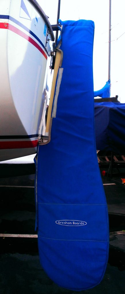
Upgrade to a Gresham Marine Cal 20 rudder and start winning races today. Proprietary rudder shape provides minimum drag and no vibration and Gresham Cal 20 rudders are minimum weight.
Rudders can be ordered with either a tube top or yoke tiller type. Tube top accepts the black anodized round tiller and the yoke tiller is made from wood and fits around the tiller.
Gresham Blades for the past 19 years have won multiple National Championships.
Installation available. Contact us for price.
Related Products

Lido 14 Rudder
Blades + Add to cart
Tiller-Custom Size
Cal 20 Parts $ 65.00 Choose Options

Cal 20 Parts $ 20.00 + Add to cart

El Toro Rudder & Centerboard
Great choice! Your favorites are temporarily saved for this session. Sign in to save them permanently, access them on any device, and receive relevant alerts.
- Sailboat Guide
Cal 20 is a 20 ′ 0 ″ / 6.1 m monohull sailboat designed by C. William Lapworth and built by Jensen Marine/Cal Boats and Calgan Marine Ltd. between 1961 and 1975.

Rig and Sails
Auxilary power, accomodations, calculations.
The theoretical maximum speed that a displacement hull can move efficiently through the water is determined by it's waterline length and displacement. It may be unable to reach this speed if the boat is underpowered or heavily loaded, though it may exceed this speed given enough power. Read more.
Classic hull speed formula:
Hull Speed = 1.34 x √LWL
Max Speed/Length ratio = 8.26 ÷ Displacement/Length ratio .311 Hull Speed = Max Speed/Length ratio x √LWL
Sail Area / Displacement Ratio
A measure of the power of the sails relative to the weight of the boat. The higher the number, the higher the performance, but the harder the boat will be to handle. This ratio is a "non-dimensional" value that facilitates comparisons between boats of different types and sizes. Read more.
SA/D = SA ÷ (D ÷ 64) 2/3
- SA : Sail area in square feet, derived by adding the mainsail area to 100% of the foretriangle area (the lateral area above the deck between the mast and the forestay).
- D : Displacement in pounds.
Ballast / Displacement Ratio
A measure of the stability of a boat's hull that suggests how well a monohull will stand up to its sails. The ballast displacement ratio indicates how much of the weight of a boat is placed for maximum stability against capsizing and is an indicator of stiffness and resistance to capsize.
Ballast / Displacement * 100
Displacement / Length Ratio
A measure of the weight of the boat relative to it's length at the waterline. The higher a boat’s D/L ratio, the more easily it will carry a load and the more comfortable its motion will be. The lower a boat's ratio is, the less power it takes to drive the boat to its nominal hull speed or beyond. Read more.
D/L = (D ÷ 2240) ÷ (0.01 x LWL)³
- D: Displacement of the boat in pounds.
- LWL: Waterline length in feet
Comfort Ratio
This ratio assess how quickly and abruptly a boat’s hull reacts to waves in a significant seaway, these being the elements of a boat’s motion most likely to cause seasickness. Read more.
Comfort ratio = D ÷ (.65 x (.7 LWL + .3 LOA) x Beam 1.33 )
- D: Displacement of the boat in pounds
- LOA: Length overall in feet
- Beam: Width of boat at the widest point in feet
Capsize Screening Formula
This formula attempts to indicate whether a given boat might be too wide and light to readily right itself after being overturned in extreme conditions. Read more.
CSV = Beam ÷ ³√(D / 64)
Embed this page on your own website by copying and pasting this code.
Discover Related Sailboats

Twenty Small Sailboats to Take You Anywhere
John Vigor turns the spotlight on twenty seaworthy sailboats that are at home on the ocean in all weather. These are old fiberglass boats...
- About Sailboat Guide
©2024 Sea Time Tech, LLC
This site is protected by reCAPTCHA and the Google Privacy Policy and Terms of Service apply.
|
|
Google, one of our third-party advertisers, may add a cookie to determine targeted advertisements based on your preferences and your visit to our site and other sites on the internet. You can choose to opt out of Googleââ¬â¢s use of cookies by visiting the Google ad and content network privacy policy .  Class Champs Keith Ives (L) and Chuck Stevens (R) (Fleet 1) L to R: Scott Atwood, Chuck Clay, and Cathy Black-Smith (Fleet 1) Jon and Debbie Thompson (Fleet 8) Phil Soma (L) and Jeff Ives (R) (Fleet 1) Kevin McCloskey (L) and Richard Welsh (R) (Fleet 4) Fred Stevens (L), Mandi Smith, and Freddie Stevens (Fleet 1) John Merchant (Fleet 1) Mike Burch (driver) and Kenny Dair (crew) trim for speed (Fleet 4) Renee Dereese (L) and Noah Stapleton (R) enjoy their trophy (Fleet 4) Dean Wyer (left) and Mile Wilder (Fleet 4) Margo Svilicich (L), Mike Svilichich (middle) & Dean Wyer (R) (Fleet 4 Rick McGregor (left) & Aaron Hall (Fleet 4) Bryan Dair (L) and Steve George (R) (Fleet 1) Cal20 Youth Movement at CBYC Chuck Clay circa 1997 Ron Wood and Van Wilson circa 1998 Cal 20 Restoration 01 Cal 20 Restoration 02 Cal 20 Restoration 03 Cal 20 Restoration 04 Cal 20 Restoration 05 Cal 20 Restoration 06 Cal 20 Restoration 07 Cal 20 Restoration 08 Cal 20 Restoration 09
|


IMAGES
COMMENTS
Cal-20 Parts Catalog. Below is a list of Cal 20 parts that we stock. Please give us a call at 510-521-7730 for current prices. Jumper strut (each pc.) Windows (pair, white high-impact plastic frames. Clear, gray-green or bronze tint) To place an order please proceed to our ordering information page. Seal's Spars and Rigging Web site.
Steve Seal was the rigger at Jensen Marine (builders of the Cal line of sailboats) from 1964 through 1969. In 1970 Steve moved to the San Francisco Bay Area and started Seal's Spars & Rigging. Steve raced Cal 20 ' s throughout the 1970 ' s, winning the national championship in 1977. Steve has also owned a Santana 22, a Cal 2-27, and a ...
Rudder Head by Boat Type. Cal 20 Parts $ 65.00 - $ 135.00 Choose Options. Quick View. Add to Wishlist. Compare. Gudgeon Special (pair) Cal 20 Parts $ 69.00 Original price was: $69.00. $ 49.00 Current price is: $49.00. + Add to cart. Quick View. Add to Wishlist. Compare. Cal 20 Tiller Yoke Wood. Cal 20 Parts $ 225.00 + Add to cart. Contact Us ...
The Cal-20 boom has so little extension beyond the measurement band the one needs to either rig an internal multi part purchases or side blocks at the end of the boom. We find ourselves utilizing the Cunningham, outhaul, Vang, sheet and backstay to shape main as well as the backstay, halyard and sheets to control the jib so take the time to be ...
Parts and accessories for Cal 20 sailboats. Boat components are subject to change. Always confirm sizes and check the product photo prior to ordering.
one design sailing for everyone. one design sailing for everyone. 62nd Cal 20 Class Championships Results. (hosted by Shoreline Yacht Club of Long Beach on July 26 - 28, 2024) Listed below are the Class Championships perpetual award recipients: • Class Champions: Jeff Ives and Phil Soma (Bravura) - ABYC. • Neil Baker 2nd Place Finisher ...
by Steve Seal. (originally published in Spyglass magazine in 1977) The California 20 was designed by C. William Lapworth in 1960 and went into production in 1961. It quickly became the most popular of the Cal line of fiberglass sailboats and 1,945 of the boats were built. Most of the production occurred throughout the 60's when the Jensen ...
You can start with Steve Seals parts catalog for the Cal 20: Seals Spars and Rigging: Cal 20 Catalog We bought rigging and gear from him, and found him very knowledgeable and helpful. Also, you can puruse our online gallerires from refurbing our '67 Cal 20, in which offending parts are named by name! Cal 20 Restoration Set 1
As the wind increases, slowly tension the cunningham to remove the wrinkles, keeping the draft at 50%. The outhaul controls the depth in the lower third of the mainsail. In light air and choppy seas, ease the outhaul 1-2 inches from the maximum tension setting. In medium air, ease the outhaul 1⁄2 inch from maximum.
Cal 20's were (and still are) inexpensive to buy, own and maintain. The base price was $3,200 throughout most of the 60's which put her within reach of just about everyone. The cockpit is nearly 8' long and is self-bailing. Below she has four bunks, a head and storage bins. For her 20' length, she is one of the most practical boats imaginable.
CAL 20 TUNING GUIDE. The following tuning guide is meant to be a good starting point in setting up your rig and sails. We are trying to achieve a setup that is fast in all conditions. Your new North Sails are designed for all around sailing performance. The Cal 20 sails best with one or two degrees aft mast rake.
CAL Sailors. CAL SAILORS HOMEManuals, Other Files and Downloads. Cal 20 Owner's Manual - 33 Pages PDF. Upload documents to share, like user manuals, spec sheets, service manuals etc. 1 post • Page 1 of 1.
Proprietary rudder shape provides minimum drag and no vibration and Gresham Cal 20 rudders are minimum weight. Rudders can be ordered with either a tube top or yoke tiller type. Tube top accepts the black anodized round tiller and the yoke tiller is made from wood and fits around the tiller. Gresham Blades for the past 19 years have won ...
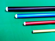
This is the original mast section used on the Cal 20, 21 and 24, and the Ranger 20. It is also the original boom section used on the Cal T-4, 27, 2-27, 28, 29, 30, and 2-30, and the Columbia 28. ... mast heads and more (see the Cal 20 parts catalog). To place an order please proceed to our ordering information page. "Jensen" Section ...
Cal 20 is a 20′ 0″ / 6.1 m monohull sailboat designed by C. William Lapworth and built by Jensen Marine/Cal Boats and Calgan Marine Ltd. between 1961 and 1975. ... The lower a boat's ratio is, the less power it takes to drive the boat to its nominal hull speed or beyond. Read more. Formula. D/L = (D ÷ 2240) ÷ (0.01 x LWL)³ D ...
30 to 40 indicates a moderate bluewater cruising boat; 40 to 50 indicates a heavy bluewater boat; over 50 indicates an extremely heavy bluewater boat. Comfort ratio = D ÷ (.65 x (.7 LWL + .3 LOA) x Beam^1.33), where displacement is expressed in pounds, and length is expressed in feet. Capsize Screening Formula (CSF): Designed to determine if a ...
The Cal 20 or California 20 was built between 1961 and 1975 by Jensen Marine. The Cal 20, designed by Lapworth in 1960, went into production in 1961. It quickly became popular due to it's low price tag of $3200 and this low priced sailboat soon became the #1 seller for Jensen Marine. Jensen Marine would soon be building a 20 footer each day !
Cal 20 Boat and Class Overview; Class Bylaws; Class Officers; Join the Class; Class Champions; Fleet Info; Cal 20 History; EVENTS; ... Long Beach Fleet 1; Cabrillo Beach Fleet 4; RESOURCES. Classifieds. Boats For Sale; Used Sails & Parts; Web Links; Tips & Tuning; General Discussions; GALLERY; Slideshow (All Photos) The Faces of Cal 20 Sailing ...
Cal 20 Rigging Guide. The Barney Post puts the mainsheet cam c/eat in a much better position. Originally this cleat was attached, under the tiller, on the seat, where the turning block is now. That placement put the cam cleat in back of the crew in a difficult place to get to. With the cam cleat on the Barney Post, either the skipper or the ...
The Cal 20 is an American sailboat, that was designed by C. William Lapworth and first built in 1961. Production. The boat ... The Cal 20 is a small recreational keelboat, built predominantly of fiberglass. It has a fractional sloop rig, a transom-hung rudder and a fixed fin keel with a weighted bulb. It displaces 1,950 lb (885 kg) and carries ...
19. Cal 20 Huntington Beach. Sep 13, 2016. #1. I got a really good deal on a Cal 20 that is sail ready! Hooked up my old trolling motor now just waiting to get a bigger battery and I will be out on the open water. Just wanted to see if there are any other Cal 20 owners out there and if anyone has any suggestions, ideas, etc thanks!
Cal-20 Parts Catalog. Description. Mast head * (less pins and sheaves, BA) To place an order please call 510-289-3325 Monday through Friday from 9 AM to 5PM (Pacific Time). Seal's Spars and Rigging Web site.
Pearson 26W Marblehead. Jan 23, 2009. #13. Part on Cal 20 Mast. Since the consensus of opinions agree its a sail feeder, and you have decided not to use it. Your probably going to need a sail stop on the lower part of the track to prevent the main sail. from dropping out of the track every time you lower it. Unless your going to remove the main.