Design Tips
In the process of designing my own model landsailers over the last few years I've learned a lot and developed a few calculations that have proven useful. Below you will find a series of mini-articles on model landsailer design as well as a few spreadsheet design tools for making simple calculations. In the interest of promoting this hobby I'm sharing these tools and advice with you.
I'm always trying to improve and add to the information here so if you have any questions about the information below or something that's not here please email me and I'll be happy to discuss it and maybe the answer will end up on this page
OVERVIEW OF DESIGN ISSUES
LANDYACHT VELOCITY PREDICTION PROGRAM

Wing Mast Experiments
- Sail Design Tool
Sail Scaling Formula
Why landsailers don't have jibs, ls mast system.
- Wheel Selection
- Bearing Selection
- Optimum Center of Mass (ballast location)
- Expected Loads
- Beam Bending Analysis Tool
- Speedometer Setup
Generating down force with rear beam
- Center of Lateral Resistance
Optimizing Length/Width Ratio for Maximum Righting Moment
General design issues.
This article is an attempt to describe the big picture of model design. In general there are two primary measurements of model performance; acceleration and top speed and the following description explains which model variables affect these two performance characteristics.
Acceleration
Acceleration is important when racing around a course when you need to change directions and get the most speed out of each gust. The very simple relationship that determines acceleration is Force = mass x acceleration. It says that a body experiencing a force will have an acceleration that is equal to the net applied force divided by the body's mass. This means that one way to increase model acceleration is to make it as light as possible. Alternatively, you can increase the net force by increasing the thrust generated by the sail or by decreasing the model drag. Increasing the sail thrust can be done by improving the sail lift to drag ratio (like using a wing mast) or by increasing the sail area. Since you need more weight to carry more sail area you can see that there must be some balance between model weight and sail area. The other way to increase net force is to reduce model drag. In practice this in not very effective because drag force is proportional to velocity squared. When accelerating from low speed these forces are small compared to the sail thrust and so body drag is not very important to acceleration. In fact, if the model is moving downwind and has not yet reached wind speed a larger body drag force may actually increase acceleration.
The conclusion is that model mass, sail lift/drag ratio and sail area are the primary variables that influence model acceleration. Acceleration can be improved only by increasing the sail lift/drag ratio and correctly balancing model weight with sail area.
Top speed is important when racing in a straight line on a long leg of a course. Calculating maximum model velocity is more complicated than acceleration but we can still determine the primary factors that influence it. Maximum model velocity occurs when the thrust force generated by the sail is equal to the combined drag force of the sail, body and wheels. Model weight has no direct correlation to maximum velocity. Instead we must consider the lift/drag ratio of the sail, the sail area, the aerodynamic drag of the model body and the drag in the wheels. Maximum velocity can be increased by improving the sail lift/drag ratio, increasing the sail area and decreasing the model drag. Because sail area must still be balanced with model mass, one way to increase top speed is to carry a large sail and make the model very heavy but this will adversely affect acceleration and maneuverability.
The best way to increase top speed, besides improving the sail performance, is to reduce drag by using low friction ball bearings in the wheels and making the body slim and streamlined to reduce friction.
Conclusions
Increasing the lift/drag ratio of the sail increases model acceleration and top speed while sail area and model mass must be properly balanced for optimum performance. In addition, reducing the model drag from the body and wheels will increase model top speed but has little effect on acceleration.
Back to top of Page
Program Description
The program described here is a Matlab script that was written to predict the speed and loading on a landyacht based on the yacht configuration, the wind conditions and the vehicle heading. To run the file you need a version of Matlab or you will need to convert the algorithm to some other language but you can at least view the file with WordPad. The algorithm doesn't make any assumptions about the size of the landyacht and so it is valid for models and full size landyachts alike. I don't have much data to compare the results to but it seems to at least be in the right ballpark for predicting yacht speeds.
The program works by guessing at and then adjusting the vehicle velocity until the net thrust is close to zero (steady state operation, i.e. top speed) for all possible headings (0-180 degrees) and sail/wing trim angles (0-60 degrees). It then stores the maximum velocity for each heading that also satisfies the criteria that the vehicle can't flip over or slide sideways. It also stores the maximum possible velocity when slipping and flipping are ignored so that you can see how close your design is to achieving it's maximum possible speed. This information is then plotted in a polar plot like the one below:
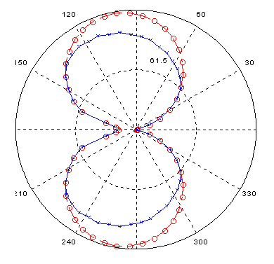
The red line represents the maximum speed when flipping and slipping are ignored. The blue line is the maximum vehicle velocity when flipping and slipping are taken into consideration. In this case, the yacht could achieve greater speeds if it were made heavier or if it made use of down force. One useful aspect of this program is that it can be used to predict how much weight is required to prevent slipping and flipping for given wind conditions and yacht configurations. Based on this information the program can also estimate the loads the vehicle will experience for any wind speed, yacht speed, rig trim and heading.
To use the program to simulate your own yacht you just need to change the yacht parameters to match your own design and run the script for the wind speed you're interested in. If you do use this program in the design of a full sized landyacht or a model, please send feedback to [email protected] along with any real data you have to compare to predictions. If you do not have access to Matlab, I will be happy to run the script for you if you provide me with the necessary yacht parameters.
To download the script right click the link below and "save as"
Matlab Velocity Prediction Script
John Horstkamp, a student at George Mason University, has translated this script to a program that can be run on any Windows machine. To download the zipped file, click here .
RIG DESIGN TOPICS
I have constructed several wing masts for the LS-3 and LS-4 platforms. The wing is similar in construction to a model plane wing with slight modifications to the trailing edge allowing for a sail slot. The balsa and basswood wing skeleton is shown below.
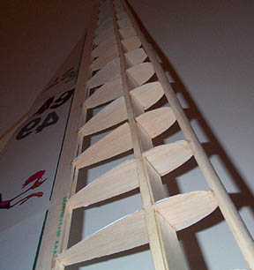
The wooden skeleton is then covered with monokote heat shrink aircraft covering to form the surface. This construction is very light, extremely strong and relatively inexpensive.
In light wind conditions (less than 15 mph) a small sail is attached using the LS-3 quick change groove system. In heavier wind conditions the sail is removed and the wing alone can be used to power the model. Though this configuration is faster than the storm sail rig it is much more sensitive and therefore more difficult to sail.
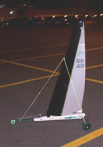
The resulting rig noticeably outperforms the standard rig reaching speeds 30-40% greater than the rectangular mast with mylar sail. To see the detailed data see the speedometer section.
The most interesting observation I have made so far is that wing thickness and tapering have no noticeable effect on wing performance. The only important variable seems to be wing area which must be balanced with the model righting moment. With this in mind, the LS-3 wing mast has been designed to provide sufficient power by itself in a 20 mph breeze. In lighter conditions the addition of the mylar sail increases the rig power so that the wing rig can outperform the stock mast and sail in all wind conditions. The LS-3 in now available with a wing mast option for a small increase in cost, and the wing mast is standard on the LS-4 .
Sail design tool
This spreadsheet is meant to make sail design a little faster. It takes a few inputs, such as luff length and rake angle, and calculates sail area, the location of the center of effort and draws a simple picture of what the sail will look like. I use it to quickly run through a few different sail plans before I start cutting. Because the materials are relatively cheap, it's a good idea to build a few sails for different wind conditions like windsurfers do.
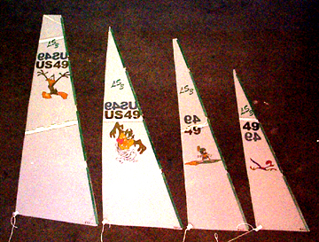
This article develops an equation for determining an appropriate scaling factor for making a sail bigger or smaller than an existing sail that is already known to work well in a particular range of wind conditions. This is intended for making multiple sails for use on the same yacht. It may not be valid for estimating appropriate sail scaling between different yachts. The equations presented assume a triangular sail shape that is scaled in such a way that the aspect ratio is maintained from one sail to the next, though this same approach could be used to derive the scaling laws for differently shaped sails as well.
Lets say you already have a sail that works great on your model in 10 mph winds and you want to make a similarly shaped smaller sail for 20 mph winds (Of course, wind is variable so when we talk about 10 or 20 mph winds, what is meant is wind conditions with an average speed near that level). To accomplish this objective, you will need to reduce the size of the sail enough that the new sail generates the same amount of heeling moment in 20 mph winds that the old one did in 10 mph winds. But how much smaller should you make it? Changing the size of the sail makes the yacht better suited for more or less wind for two reasons. First, the sail size affects the sail area, which governs the magnitude of the forces generated by the sail. Second, the sail size also affects the location of the sails center of effort, which governs the effect that the sail force will have on the yacht. Because the center of effort changes, the mast step will also have to be shifted either forward or backwards to maintain proper helm balance. Another result of this effect is that since a smaller sail will have a lower center of effort, it can generate higher forces before exceeding the yachts maximum stable heeling moment. This means that more thrust can be generated before the yacht will tip, which is one of the reasons that yacht speed increases as wind speed increases.
Scaling Equation
S - sail scaling factor you want to compute (scaling of each sail dimension)
R - ratio of new design wind speed to old design wind speed (in this example R = 20mph/10mph = 2)
The following is a scaling equation for a triangular sail shape (click here for derivation):
S = R^(-2/3)
When plotted this function looks like this:
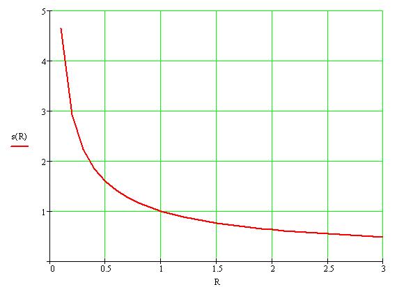
There is also an excel worksheet that will perform this calculation for you: click here.
An example of how to use this formula will now be presented. Although in this example, the formula is used to scale down, it can also be used to scale up. Assume you already have a sail that works well in 10 mph winds with the following dimensions:
Original sail dimensions:
Foot (triangle base b) = 10 in
Leach (triangle height h) = 50 in
Area A = 250 sq. in
Now you decide that you would like to make a new sail that will generate a similar heeling moment in 20 mph winds. The variable R is 20 mph/10 mph so R = 2. Using the above equations or plots, when R = 2, S = 0.63. Now we multiply the original sail dimensions by S to get the new dimensions:
New scaled sail dimensions:
Foot (triangle base b) = 10 in x 0.63 = 6.3 in
Leach (triangle height h) = 50 in x 0.63 = 31.5 in
Area A = 99 sq. in
While this method does not take into account differences in mast bend, Reynolds number and other secondary effects, it should provide a very good estimate for scaling up or down from an existing sail configuration. Once the mast step is repositioned properly, this new sail should behave similarly in 20 mph as the original did in 10 mph winds.
It seems that every soft water sailor who contacts me asks why my models don't have jibs.
To understand the difference between soft water sailing and landsailing you must think about working in an entirely new realm of speed where the effect of apparent wind actually exceeds the true wind. Because the resistance to forward motion is so small on a landsailer, it will quickly reach wind speed at almost any point of sail other than head to wind. At that point the vehicle speed will increase further based on the combined effect of the true wind added to the apparent wind. This makes it possible to reach speeds in excess of 3 times wind speed! This means that once under way, a landsailer (even a model) is essentially going upwind no matter what it's angle to the true wind.
At these high speeds and low angles of attack a single sail rig is vastly superior to a multi sail rig because it can generate a higher lift to drag ratio than multiple sails. This is why you will never see a modern land yacht with a jib (see http//www.nalsa.org/ ) or a bi-plane for that matter. The same reasoning applies for models. When you're sailing a monohull these effects are not apparent because of the limits of hull speed, but you don't need to be going 60 mph to see this effect. If you've ever sailed on a modern beach catamaran you know that in an upwind leg a jib is often a hindrance which is why the fastest cats use a single, wing like main sail for upwind work and a retractable reaching sail for downwind work.
I hope this explanation satisfies anyone's urges to try a jib on their land yacht. While I enjoy and encourage experimenting with new rigs and configurations to enhance model performance this is one test that has been done many times before. Why not try a wing instead!
Since I've heard quite a few questions about my spring loaded side stays I've provided a short description below.
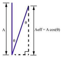
As it turns out, I've found that model performance is also very dependent on rig tension. Specifically, the model is much faster when the sail leans to leeward. This behavior is much harder to explain, but I'll try.
These figures try to show the difference in the vectors of the air flow over the sail for a vertical and tilted configuration.
With the sail vertical, the air is forced to flow approximately parallel to the foot of the sail so that the resultant forces on the model are to leeward (which causes sliding) and forward (to cause forward acceleration).
When the sail is leaning to leeward, the air flows upwards and to leeward (parallel to the mast). That results in two forces down and to windward that weren't present when the mast was vertical. This additional force to windward (which counteracts the leeward force and improves balance) may explain the better performance of the tilted rig.
PLATFORM DESIGN TOPICS
Wheel selection (urethane inline skate wheels vs. foam RC plane wheels)
I have also tried both types of wheels and there are three main reasons I feel urethane wheels are better than foam plane wheels for model landsailers.
And now thanks to the increased popularity of foot scooters urethane wheels with diameters of 125 mm and even larger are now available.
If you are planning on purchasing inline skate wheels I recommend the closeout deals at www.skatepro.com
Bearing selection
There are many grades of bearings available for roller blade wheels and I have tried several to determine the impact of bearing quality on model speed. Delrin bearings range in quality from ABEC 1 to ABEC 3, 5 and 7 with ABEC 1 being the slowest and cheapest (about $1 each) and 7 the fastest and most expensive (about $2.50 each). There are also ceramic bearings available that are even faster and more expensive ($5 or more each).
When used on inline skates or skate boards you can notice great differences in bearing performance because each set of bearings is supporting 20-40 pounds. On a model landsailer each set of bearings supports about 1-2 pounds. This small load makes the advantages of "better" bearings much smaller.
To test the effects of bearing quality on model speed two identical LS-3 's were raced. One was fitted with ABEC 1's and the other with ABEC 7's. The result was that the LS-3 equipped with ABEC 7's had a slight advantage in wind conditions from 5-8 mph though it was barely noticeable. In winds in excess of about 8 mph no difference could be noticed.
These results lead to the conclusion that high quality bearings may be slightly advantageous for racing but do not have as much effect on speed as other features such as beam, mast and sail configuration.
Optimum Center of Mass
This section describes the best way to position weight on your model in order to counteract the force of the wind on the sail. This approach does not take into account the effect of weight distribution on model balance and vibration which should also be considered.
On a landsailer, as with any wind powered vehicle, it is beneficial to minimize overall weight to increase acceleration. Of course, some weight is required to counteract the force of the wind that tries to flip the vehicle over. How this weight is distributed determines how much righting moment (the thing that keeps you from flipping) you have per unit mass. The goal is to maximize the righting moment per unit mass so that you get the most benefit from the weight you carry. In the LS designs overall weight is minimized first and then the majority of the model weight is concentrated in the area that yields the most righting moment.
There are two methods for determining the optimum weight distribution and both lead to the same conclusion. Both methods are described below.
The results show that the best place to put the majority of the model weight is a far to the stern as possible. Furthermore, whether you concentrate the model weight at the ends of the rear beam or at the center, there should be little difference as long as the weight is balanced side to side and is far rear as possible.
Energy-Work approach
One way to approach this problem is to say that the rig must do some work on the mass of the vehicle to lift the windward wheel. If the goal is to prevent this from happening, then lifting the windward wheel a given amount should require as much work as possible. Work (or energy) is equal to force times distance. In this case, the force is the weight of the vehicle and the distance is the height that weight is raised off the ground.
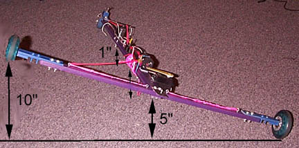
To maximize the energy required to lift the wheel for a given model weight all the weight should be put where it will move the most as the wheel comes off the ground. Based on the geometry of a 3 wheeled landsailer, this distance is largest at the rear of the model near the windward wheel. Since the weight must also be symmetrically distributed for vehicle balance we can consider two cases:
If all the weight (let's say 2 pounds) is at the center of the rear beam then the work done is 5" x 2 pounds = 10 inch-pounds total.
If there are two equal weights (1 pound each) located at each end of the rear beam then the total work done is 10" x 1 pound = 10 inch-pounds total. The other pound of weight doesn't contribute because it doesn't move as the vehicle tilts. The result will be the same if the 1 pound weights are located any distance from the center as long as they are symmetric.
So as long as the weight is far rear it doesn't make any difference how you distribute it along the rear beam as long as it's symmetric.
Moment approach
We can also model the sail as exerting a moment on the model that must be counteracted to keep the model from flipping (or forcing you to let out the sail). In this case we want to maximize the moment exerted by the model weight. Since moment is distance times force you want your weight in a place where it is far from the point of rotation (the leeward rear wheel).
For example, say your beam is 30" long. If you put 1 pound of ballast at each end of the beam then as the windward wheel lifts off the ground the weight at the leeward end does nothing to counteract the sail force because it's not moving. The weight at the windward end it being lifted and is 30" from the rotation point so it exerts a moment of 30 inch-pounds (1 pound x 30") keeping you from flipping.
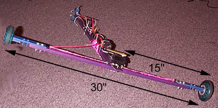
Now consider if instead of 1 pound at each end, you put 2 pounds in the center of the beam. As the windward wheel lifts off the ground all 2 pounds will move but now the moment arm is only 15" long and so the total moment is still 30 inch-pounds (2 pounds x 15").
So once again, as long as the weight is far rear it doesn't make any difference how you distribute it along the rear beam as long as it's symmetric.
Expected loads
By analyzing the failure mode of an early model, I was able to estimate the maximum load you can expect the main beam will have to support which can then be used to get an idea of how strong you need to make it.
In this case, a composite balsa/basswood I-beam fractured from the force of the sail pushing down on it.
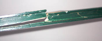
The wind was blowing approximately 20 mph when this beam failed just forward of the mast step. Based on the material properties and the loading geometry, I found that the force exerted on the beam by the sail must have been at least 25 lbs. The area of the sail being used was 250 in 2 . So assuming this force increases linearly with sail area (which is probably a good approximation) this should give you a rough idea of how much load your model must support for a given sail area in 20 mph of wind.
Bottom line: To get a rough idea of how much load your beam will see in a 20 mph breeze, take your sail area in square inches and divide it by 10 to find the expected load in pounds.
Beam bending
This spreadsheet is an aid in designing beams for the main spar, rear beam and mast cross sections. It helps calculate the bending of a simple wooden beam for a given loading situation and could be modified to work for more complex structures and different materials.
Speedometer Experiments
I've been working on a system to more accurately measure model speed. To refine the measurement, I've purchased a bicycle cyclometer and fastened it to one of the rear wheels as seen in the accompanying pictures.
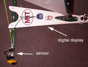
This cyclometer is an avocet cyclometer model 15 which was chosen for its capability to be programmed for wheel circumferences as small as 100 mm eliminating the need to convert the display's velocity read out. This model also has a maximum speed function which is required on a model if you wish to see how fast you were going.
The system is relatively cheap and simple to put together but the initial results were disappointing. The speedometer hit a limit at 11.2 mph, and was incapable of measuring any higher speeds on the 80mm wheels. Since the recommended sensor position is 3" from the axle with a top speed measurement of 75 mph, and on the model it was mounted approximately 1" from the axle, the maximum speed expected is about 25 mph. This suggested that there was a mounting/alignment problem that needed to be corrected before an accurate velocity measurement could be made.
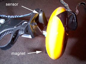
The magnet was remounted on a larger 110mm urethane wheel and the maximum speed increased to 15 mph but did not work at higher speeds as you can see in the following plot.
Preliminary results are shown here for the LS-3 with the standard sail (pink) and with the developmental wing mast (blue) though no data has been taken yet in winds over about 9 mph. The horizontal axis represents wind speed and the vertical axis is model speed. As you can see the LS-3 exceeds wind speed by 50-100% and may even do better in higher winds. The velocity curves fall off at higher speeds because the speedometer is currently not capable of measuring speeds greater than 15 mph.
Traditionally in any sailing vehicle the only force that is used to counteract the sail and keep the vehicle from flipping over is weight. An alternative is to generate an aerodynamic force (down force) to counteract the sail. In most sailing vehicles the air velocity simply isn't large enough to easily generate significant amounts of force but on a model landsailer apparent wind velocities can easily reach twice wind speed. This makes it possible to use the model's rear beam to generate an appreciable down force (about 1/4 to 1/3 of the model weight). This can be accomplished by making the rear beam in the shape of an asymmetric airfoil. The drawback is that an asymmetric airfoil creates more drag than an equally sized symmetric foil.
To determine if the benefits of this design outweigh the extra drag the performance of the LS-4 prototype design was simulated for a symmetric rear beam and a down force generating asymmetric beam. The polar plot of vehicle velocity vs. wind angle is shown below for both designs in a 20 mph breeze. The result is that the asymmetric design, shown in blue, is slightly faster (about 1 mph) than the symmetric design for most points of sail. Both designs are predicted to reach speeds of 28 mph using the wing mast alone in the 20 mph breeze.
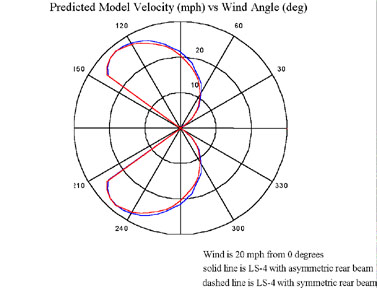
During some initial tests on the prototype LS-4 this technique seems to have some large benefits. The result is a much more stable model with no noticeable affect on top speed. This is possible because the slight increased in air drag is balanced out by the fact that the model can safely carry more sail area and use more of the existing power to generate more thrust without flipping.
Locating the Center of Lateral Resistance
Lateral resistance is the force or forces that oppose sideways motion in a yacht (land or otherwise). It is important to know where the center of lateral resistance is so that you can position the sail's center of effort nearby to control the helm (the tendency of the yacht to turn up into the wind or down away from the wind when you stop steering). In the case of a boat, the lateral resistance is provided by the hull and the foils (i.e. rudder and center board). On a landyacht, the friction between the wheels and the ground provides the lateral resistance. The center of lateral resistance (CLR) is the point along the length of yacht where, if you push it sideways, it will slide sideways without rotating. You can also think of this point as the place where all the lateral resistance force would be acting if it was only a single force, rather than forces on several different wheels. To find out where the CLR is on your yacht, set it up on the ground and push it sideways with your finger. Search for the place where the boat doesn't rotate as you push it. It turns out that on a landyacht, under static (i.e. non accelerating) conditions, the center of lateral resistance will be the same as the center of gravity (CG), provided that the coefficient of friction for the front and rear wheels is the same. The figure below shows the static force and moment equations for a landyacht.
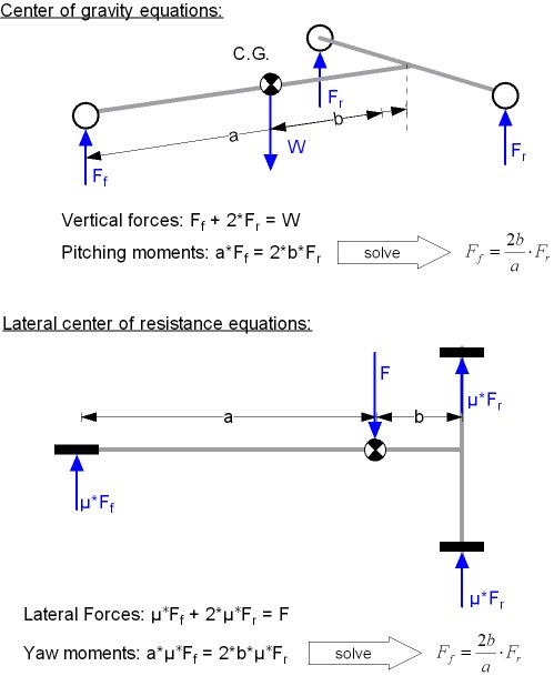
These equations show that the CLR and the CG are the same as long as the friction is the same for all the wheel. If the friction at one wheel is greater than at another, then the CLR will be shifted towards the wheel with the higher friction. Once you start sailing, the forces on the sail will have an effect on the weight carried by each wheel, which will also shift the CLR slightly. That is why the static determination of the CLR may only be good enough for a first guess at where to place your sail for proper helm. After that, you will probably need to experiment a little to find the position that gives you the helm you want.
The length-to-width ratio (L/W) of a three-wheeled landyacht affects the righting moment available to keep the yacht from flipping. This is because the moment arm (the distance from the center of gravity (CG) to the line about which the heeling yacht rotates) changes as the L/W ratio changes. The figure below demonstrates this.
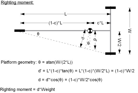
The distance "d" in this figure is the moment arm and as you can see, as the yacht gets very long (L/W -> infinity) d approaches half the rear axle width (w/2). As the yacht becomes very short (L/W -> 0), d approaches zero. This relationship is demonstrated in the following dimensionless plot.
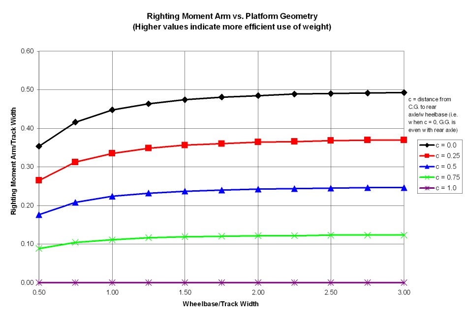
The plot shows that for small L/W ratios, the righting moment arm increases quickly and then levels off. Based on this analysis, you might think that the longer you make your yacht, the better, although most of the benefit is had once you get to L/W = 1.5. It also shows that as the CG moves backwards, the righting moment increases. However, the previous plot assumes that the CG can be moved independently of yacht length, but in reality the CG will move forward as the length increases. Exactly how much the CG will move depends on the specific design of the yacht. To quantify this relationship, the LS-3 design was chosen to determine the approximately relationship between length and CG position. This next figure shows the normalized moment arm (d/w) when we account for the relationship between length and CG position (based on the LS-3 design).
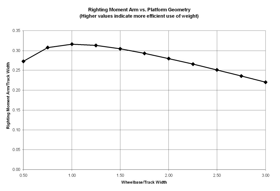
This shows a more realistic picture of what is happening as the L/W ratio changes. Now you can see that the maximum righting moment arm is reached at an L/W ratio of about 0.8 to 1.3. However, L/W ratios at or less than 1 have undesirable behavior because the fore-aft stability becomes an issue when the windward wheel begins to lift off the ground. A good compromise is an L/W ratio around 1.3-1.5, which is a value commonly seen in full scale landyachts and models alike. In fact, the IRCSSA class rules, when maxed out, result in L/W ratios of 1.3-1.5.
More to come soon... And if there is an aspect of model design you would like to discuss, please send your suggestions, questions or comments to [email protected]
HOME PAGE | PRODUCTS | PRICE LIST | PHOTO GALLERY & VIDEO CLIPS DESIGN TOOLS & TIPS | RELATED LINKS | FAQ's
KRIS SELUGA | MILFORD, CT | [email protected]
- Information
- MIA Virtual Museum
- Purchase Agreement
- Ordering and Shipping
- Contact Us


3D Printed Folding RC Land Yacht - MUSHU

Introduction: 3D Printed Folding RC Land Yacht - MUSHU

This instructable goes through the process of creating a folding RC land yacht through 3d Printing.
This project fits into the IRCSSA class 1 rules (http://ircssa.org/class-standards/) which is a development class of RC land yacht using a box rule (all of the vehicle must fit within 750mm length x500mm width x 1000mm height) This land yacht is designed as a fun simple project to get into RC sailing and 3d printing, not as a regatta leading race machine.
I will walk through the steps of designing this yacht, the principles of which can be applied to custom designing your own land yacht. Feel free to do this if you have the CAD knowledge or take my parts and print these as they are.
For simplicity I have used a mast and sail from an easily accessible RC yacht class. The parts for this could be replaced by a cheaper home built assembly but lightweight and quality masts and sails will make for a better performing boat. The only part that would need to be modified is the mast step which currently accepts a 5mm tube.
The name of this design 'MUSHU' came in part from the rig. The mast and sail are from a Dragon Force 65 (DF65) RC yacht. This project is for the land though, so the first land dragon that came to mind was Mushu from Mulan that has been a regular at my house with a soon to be 3 year old running around.
If you have any questionsn about the project feel free to message me or comment on this instructable.
- 3d Printer or access to someone with one.
- Lighter or matches
- Drill and bits
- Adjustable Spanner
- Phillips head screw driver
- 3d printer filament (approx 300g used)
- Aluminium bar 10mmx3mm section approx 1m needed
- Dyneema cord 3m - https://www.hobbywarehouse.com.au/joysway-881204-df95-0-6mm-dyneema-cord-10m-length.html
- 6x 4Gx9mm screws (to attach servos)
- 2x 8Gx16mm screw (rear wheels)
- 8x M3x20mm bols (to join hull parts and Aluminium bars)
- 6x M4x10mm bolts + nuts (to join Aluminium bar to hull)
- 2x M5x30mm bolt (for Front wheel assembly)
PURCHASED PARTS
- 608 Bearings - https://www.kogan.com/au/buy/acosecommerce-10x-608rs-skateboard-roller-scooter-sealed-ball-longboard-skate-bearings-wheels-dks-sk8-wheels-10x/
- Sail Servo - https://www.hobbywarehouse.com.au/joysway-83014-servo.html
- Steering Servo - https://www.hobbywarehouse.com.au/dynam-17g-servo.html
- On/off switch - https://www.hobbywarehouse.com.au/joysway-881529-dragon-force-65-v6-switch-rod-with-rubber-bellow-and-switch-connector-set.html
- Bowsies - https://www.hobbywarehouse.com.au/joysway-881210-df95-bowsies-pack-of-10.html
- Trasmitter & Receiver pack - https://www.hobbywarehouse.com.au/joysway-880515.html
- Battery Pack
- Reusable batteries to fit above + Charger
- DF 65 B rig assembly - https://www.hobbywarehouse.com.au/joysway-880563-df65-v5-complete-b-rig-assembly.html
- DF 65 B rig Sails - https://www.hobbywarehouse.com.au/joysway-881510-dragon-force-65-v6-b-printed-mylar-sail-set.html?gclid=Cj0KCQiAjc2QBhDgARIsAMc3SqThDtDNUXOsHUjNt05B7USZmftN0spW6BOD--vNNPlIB6P5TDnDolAaAoU2EALw_wcB
Step 1: Design (Skip If Using Provided 3d Print Files)

The first step in designing this land yacht was assembling all the required RC gear. This really dictates the layout and physical size of your land yachts ‘body’
For a functional land yacht you only need a very basic RC setup:
- 2chanel transmitter & receiver
- 1x battery pack
- 1x servo switch (on off switch)
- 1x steering servo (i used a 17g servo)
- 1x sail control servo (I used a 37g servo)
If your like me you wont be able to resist plugging everything in and seeing how they move… Go for it. This will help you see what your servo’s range of motion is.
Playing around with different layouts for the parts early on helps get an idea of what the body shape could be to accommodate all the RC gear. The second image in this step with multiple assembled layouts shows a couple of different options I played with before settling on the compact option at the bottom.
Once I had all the parts assembled I arranged them roughly where I thought they could go and measured the overall dimensions. This became my guide for the body (see plan view sketch image). with key internal dimensions.
My final shape looks a lot more refined than the orange box shown in the images. However these early prototypes were really helpful to see the RC parts inside this box. This showed me which areas had heaps of extra space, where wires could run etc and from that I was able to remove some of this empty space and create a more curvy design (See sketch and two part image)
While this shape worked and everything fit inside nicely, I wasn't happy with the amount of support material needed to print the hull. I changed the model and turned the two part hull into a three part hull. This meant that very little support material was needed for the print, but the model now could be printed with a coloured middle section adding a bit more interest to the project. Win win! (See CAD images)
Figuring out how to join the main hull to the wheels was relatively straightforward. I had some Aluminium 10x3mm solid section spare from another project that I wanted to use. I designed the additional parts to accept these with small bolts used to hold them in place. There was a lot of trial prints to get all of this right. The final image shows a bunch of the bits and peices that I printed on the way to the final design.
For the Wheels I made my own hubs to take some bearings in an attempt to get them running a bit smoother. The sizes of some of these parts will vary depending on what wheels etc you have on hand. I made my wheel hubs fit these tires - https://www.amazon.com.au/gp/product/B09D3NNGKJ/ref=ppx_yo_dt_b_asin_title_o04_s00?ie=UTF8&psc=1
Feel free to use whatever wheels you can get your hands on. I have read a lot of guides on roller blade wheels being ideal for RC Land yachts.
Step 2: Print All the Parts!

If you are going to design your own parts then you have quite a few hours of fun ahead of you. Otherwise use the parts attached here that I have designed and you have quite a few hours of printing ahead of you!
Most of these pieces have been designed to print without support. See below at the end of this step for quantities, support and infill settings that I used. Feel free to play around with these settings as you see fit. I haven’t had any breakages from the parts on this prototype to date.
Clean up any of your prints that need it with a bit of sandpaper or files. I have left most of mine as they came of the printer as i’m not too worried about the print quality. I printed my parts on an Anycubic Mega Pro with only minimal tuning to date - One day i’ll get better print quality but i’m happy with this for now.
Check all of your nuts fit into the allocated holes on the printed parts, as well as your mast and any bolts.
Most of the nuts should be a bit of a pressure fit but if you want to make sure they always stay in place feel free to take some superglue and fix them in place.
Printing quantities and support:
All parts .16mm layer height. .2 infill.
Hull bottom - 1x. Needs supports for where the steering servo goes only.
Hull middle - 1x. No supports
Hull top - 1x. no Supports
Rear wheel axle - 2x. No Supports but print vertically
Fron twheel attachment point - 1x. No Supports
Front wheel bracket - 1x. No Supports
Front Wheel Axle - 1x. No Supports
Front wheel lock nut - 1x. No Supports
Wheel Hub - 3x. No Supports
M4 Lock nut - 3x. No Supports
Attachments

Step 3: Cut Aluminium Bar

Take your Aluminium bar and cut two lengths at 227 mm long and one length at 400mm long
Give the ends a bit of a sand or file to clean up any scrappy bits your hacksaw may have left.
Dry fit the Aluminium bar into each of the parts that join together and mark holes using the 3d printed parts as a guide to mark where your holes need to be drilled. (check the images later in this instructable if you arent sure where these parts need to line up)
Use a punch and make a point on the Aluminium to help center the drillbit when drilling out holes in the bar. This step helps stop the drill bit from wandering off your mark and leaving your hole drilled out of place.
Drill out each hole and test the fit with your 3d printed parts and nuts and bolts. If need be drill the holes larger to fit everything together.
Step 4: Assembly RC Parts & Hull

Firstly before fitting all the RC gear and bolting the hull parts together, attach nuts inside the base of the hull. Use a little bit of superglue to hold these in place. You won’t be able to access these later in the assembly.
Assemble the RC gear inside the hull. It’s a good idea before you screw the hull together to test the RC gear is all working as desired, Which port on your receiver will determine which control on your transmitter is used to adjust it. Check your transmitter/ receiver manual for information on what to plug in where, also for info on how to ‘bind’ your transmitter to your receiver. Make sure you do this!
With 4xM3x20mm bolts assemble the three parts of the hull together. The fit is tight enough that no nut is needed on the end of these bolts.
Fix the servo’s in place using 4g x 9mm screws. Pan head or countersunk head both work here.
Step 5: Join Aluminium Bars

Flip the hull over and attach the long Aluminum bar to the front of the hull, and the shorter pieces to each side. You can tighten the front two bolts as this won’t move again but make sure the bolts on the arms are firm but not overly tightened. These two bolts as shown are the pivot points when the arms are to be folded up.
Attach the last two points with your M4 lock nuts (See the last image). These are designed to be large enough to screw together by hand. These bolts unscrew to allow the arms to fold in for transport when the rig is off.
Step 6: Assemble Front and Back Wheels

Both back wheels use identical parts and should be assembled as shown (First image). Take the wheel bearing and press this into the tire hub. The inner ring on the bearing will fit over the round part that attaches to the aluminium bar (axel bracket). Fix these in place using a 8Gx16mm pan head screw as shown. Fix the axle bracket to the aluminium bar using a M3x20mm nut and bolt. (You can use smaller bolts in some parts or cut these bolts down but for this instructional i've tried to keep the different sizes of bolts to a minimum)
Assemble the front wheel assembly as shown (Second image) The front wheel uses two M4x30mm bolts, one as the wheel axle and one to attach the steering pivot point to the front bracket that attaches to the Aluminium bar.
Attach your steering arm to the steering servo and attachment point at the front wheel assembly. This might need some fine tuning to get the right amount of turn out of your servo. To get started I used two steering servo arms with attachement points like the one shown here. Then i Taped the two bars together with some duct tape as a temporary hold. This allows you to make some adjustments if need be.
Turn your RC gear on here and let the steering servo center. Unscrew the servo arm and re-attach this in place with the front wheel centered. You should now be able to turn the wheel in both directions an equal amount.
When we get sailing you may find that you need a longer arm on your servo or to use an attachment hole on the front wheel assembly close to the pivot point to get more turn. My turning circle was quite large at first but with some adjustments i'm happy with the turning now.
Step 7: Attach the Rig

Using some fine string (dyneema cord that is used for many model RC yachts is ideal) Attach a jewelry clip or similar clip to both the back aluminium bars and the front aluminium bar. These serve as attachment points for the stays that hold the mast in place.
Tie a reef knot https://www.youtube.com/watch?v=aprfVTaxkk0 to attach this little bit of string and burn the ends of the rope to avoid fraying. Dyneema cord will burn easily so go careful with your lighter here.
Take your Donor mast from your DF65 or similar and fit it into the attachment point on the hull. Attach a forestay and two side stays. And pull them both back to where they attach near each wheel. Tie a loop in the end of one making sure that you are putting a bit of tension on the mast (pulling it backwards) when this loop attaches to the jewelry clips. Pull both stays back to the centre of the boat and tie the other stay at the same length as the first. This will help ensure the stays pull the mast symmetrically backwards. Clip both of the stays into place.
Attach a bowsie to the lower end of your forestay and tie this off so that you can put tension on the mast. Attaching cord to these bowsies can be a bit tricky and needs a nice clean cut on the tip of your cord. If you are struggling with these check out some YouTube videos on tips and tricks for bowsies.
For the final rigging step attach another bowsie to some cord tied to the end of your boom. Attach the other end of this to a jewelry clip or similar and tie a loop of string onto the end of your sail control servo. Make sure to give enough play when fitting the bowsie that your sail can be pulled tight when the servo arm is pulling as tight as it will go as shown in the below image.
All off your rigging is now complete and can be quickly assembled and disassembled by loosening the bowsies and unclipping your jewelry clips.
All that's left to do now is go sailing!
I will be working on a box for my boat to safely store the sail away from damage. Two pieces of cardboard and some tape will do for now!
Hope you have enjoyed this intractable and I welcome any comments or feedback.

Second Prize in the First Time Author Contest

Recommendations
![model land yacht Tim's Mechanical Spider Leg [LU9685-20CU]](https://content.instructables.com/FFB/5R4I/LVKZ6G6R/FFB5R4ILVKZ6G6R.png?auto=webp&crop=1.2%3A1&frame=1&width=306)
Made with AI - Autodesk Design & Make - Student Contest

For the Home Contest

Text Contest

- Classifieds
- Remember Me Forgot Password?
- Boats Sailboats Discussion LS-1 Land Yacht Plans?
- Electric Flight
- Advertising
- Our Sponsors
- Review Policies
- Terms of Service
- Privacy Policy
- Site History
- Mark Forums Read
- Member Search
- Upcoming Articles
- Do Not Sell My Data
- Manage Consent
- Back to Top
- Recent Orders

- Free Delivery Over £100 UK Mainland
- Join our CMB Club - Get 5% Off
- Here to help on 01840 211009

Pacer Land Yacht (Model Plan)

- Description
Semi scale land yacht, length 900mm and cross width 560mm. Uses standard RX and servos for steering and sail control. Construction in balsa and ply shown on plan. Designer Chris Reid. Featured in: Free Plan in January 2003 MMI 2 Star Difficulty Rating

Ask a question about a product
- Full Name *
- Confirm Email * *
- Your Question
Best Sellers

RRP 2.94 You Save £0.44

RRP 2.75 You Save £0.42
New products.

Recently Viewed
Please select next action
Go back ( or ) Go to wish list

Luxury motorhome
high end motorhome

high-end motorhome

luxury motorhome

high end RV

Meet us at Düsseldorf Caravan Salon.
Have you recognized the difference between good and the best, even when it comes to the smallest differences?
August 27 - September 04, Caravan Salon Düsseldorf - Hall 5 / C07
- Skip to primary navigation
- Skip to main content
- Skip to primary sidebar
- Skip to footer
Journey With Confidence

The Airstream Land Yacht is One Trailer You Have to See
- New RV Products and Gear
- RV Trailers and Motorhomes
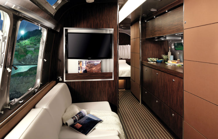
To strengthen the Land Yacht theme, Airstream consulted with Mauro Micheli, the acclaimed yacht designer for prestigious Riva Yachts
Airstream has an interesting history of building Special Edition models. In past years, they have offered the contemporary Eddie Bauer Edition as well as the rustic-themed Pendleton National Park Service Edition. One of the latest selective models to be conceived – and a departure from its other special trailer predecessors – is the Land Yacht 28, which was introduced in late 2014 and has achieved plenty of attention across the highways of North America.
Every special edition model that the company devises carries a distinct theme. What makes the Land Yacht so unique this time around is it was inspired by Airstream leaders of past and present – late company founder Wally Byam and current President and CEO Bob Wheeler as both share a passion for recreational sailing. As Byam inspired many traditional Airstream designs from his passion of travel – on and off the water over the years – Wheeler and his design team commemorated that passion into the Land Yacht 28.
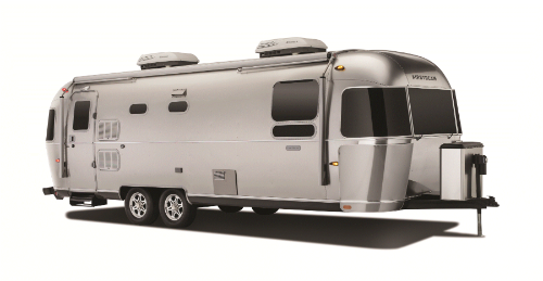
The exterior of the Land Yacht.
To strengthen the Land Yacht theme, Airstream consulted with Mauro Micheli, the acclaimed yacht designer for prestigious Riva Yachts and co-founder of Oficinia Italian Design firm based in Italy. The results were the iconic Airstream profile on the outside with a clean, modern and stylish interior with several forms of function on the inside.
“The Land Yacht is unique as we teamed with Mauro Micheli,” said Bryan Melton, General Manager, Travel Trailers for Airstream, Inc. “With our engineering input, he and his team created the design elements. Our goal was to have a super clean, beautifully appointed interior with attention to every detail. For example, he designed the fridge and freezer to be concealed behind a padded panel, while the cooktop and sink in the galley are concealed with a wood enclosure and built-in aluminum back splashes. They are all hidden providing a refined appearance, yet are easily accessed when they need to be used.”
“Airstream’s Bryan Melton explained that only 45 Land Yachts were scheduled to be built when the model was first introduced. There are only 12 left in the market place across North America and the last one – number 45 – will be completed at the end of September.”
Other key appointments are found in the lavy. While it’s not uncommon for Airstream trailers to feature the shower and toilet/sink in separate areas of the unit, the Land Yacht has an all-encompassing lavy with the essential components in the same space – with fit and finish executed to the tiniest of detail. Another functional design includes the master bedroom. It comes complete with a power memory foam, pillow top queen mattress, plus under bed storage, however, the standard 30-inch flatscreen TV is cleverly located behind a two-way mirror allowing two common functions in one small area.
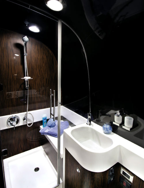
The all-encompassing head that includes a shower, sink, and toilet in one ideal location.
Some Land Yacht Standards Include:
• A powered solid wood dinette table* • Power stabilizers • A premium awning package • Comfortable, convertible seating • Power entry steps, • Induction cooktop • The Quietstream A/C unit* • Interior hardware* • A new bathroom design* (*Airstream Firsts)
“With its features, the Land Yacht has a heavy designer influence that makes it incredibly clean and unique with a strong yacht theme, while still making it functional, practical to use,” said Melton. “That’s really what it’s all about. Special editions are meant to take us outside our comfort zone allowing us to set new boundaries. The reward comes from our customers who are seeking something a little different, and our special edition models provide just that.”
Melton explained that only 45 Land Yachts were scheduled to be built when the model was first introduced. “We build only two a month and have since we began this Special Edition,” he explained. There are only 12 left in the market place across North America and the last one – number 45 – will be completed at the end of September.
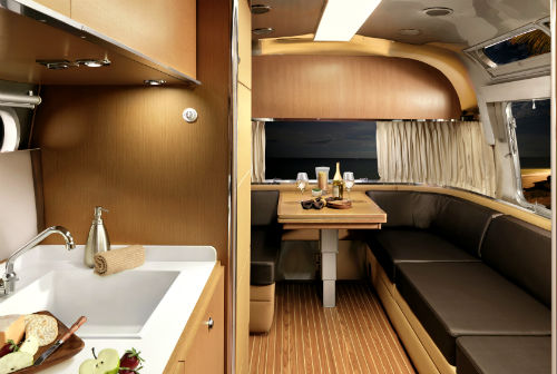
The Land Yacht is available in two interior colors, Mocha (seen Here) and Polar (shown at top).
“The Land Yacht is kind of an ode to the olden days of Wally (Byam) with his dream and passion of travel, adventure and sailing,” explained Melton. “This model represents the most luxurious Airstream model, with fine detailing and design elements throughout. Once #45 rolls out of the factory, we will temporary suspend the famous Land Yacht badge.”
While Special Edition models from Airstream (including the Land Yacht) have a scheduled life span in the consumer marketplace, the influence and design that are incorporated into these models commonly stay within the Airstream brands. There were a series of features introduced in the Land Yacht, with the most popular being the Quietstream ducted A/C, which has become standard on all but the Sport Airstream models.
“It doesn’t come down to how many Special Edition units we sell, it’s about creating truly unique models that allow our team, and those we partner with a creative outlet to try new ideas.,” said Melton. “When you remove certain constraints, you allow engineers and designers to maximize their creativity. The results are truly special, like the Land Yacht, which continue to make strong statements within Airstream’s prolific history.”
If you have any questions about the company`s Land Yacht Design or wish to join in on the Airstream discussions with other owners be sure to go to AIRForums.com .
Specifications
Length: (exterior):28′ Width: (exterior): 8’5.5″ Height: (exterior) : 9’9″ (w/A/C) Interior width: 8′ 1″ Interior height: 6’6″ (w/A/C) Hitch weight: 842 lbs. (w/LP Batteries) Unit Base Weight: 6,586 lbs. (w/LP, Batteries) Gross Vehicle Weight Rating: 8,200 Net Carrying Capacity: 1,614lbs. Fresh Water Tank: 39 gal. Gray Water Tank: 37 gal. Black Water Tank: 39 gal. Water Heater w/electronic ignition: 6 gal. Ducted Furnace: 25,000 BTU Sleeping Cap: 1-5
Racing Sparrow Plans
Check out these plans and resources, ranging from a 375mm boat to a 1500mm yacht. Pair these with our eBook guide for a fast, easy, and affordable home build RC yacht.
RS-RG65 - 650mm plans, measures to international RG65 rules
A full forward hull and a straight stern. This boat has proven to be a very fast and competitive racer.
Free Book Sample - PDF
A few pages from the eBook absolutely free
Racing Sparrow 750 plans
The plans that come with the eBook.
Racing Sparrow 1000 plans
A one metre version, scaled up lines. Bulkhead only plans. Look at the 750 for full schematics.
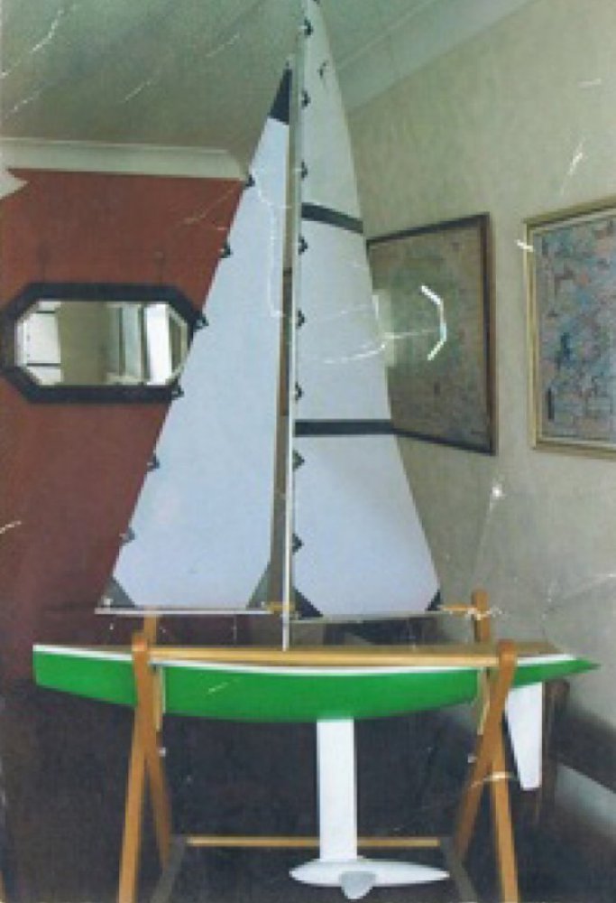
Racing Sparrow 1500 plans - A scaled up Racing Sparrow
A larger size model yacht. I haven't seen many of these surface. It's a good challenge to build.

Racing Sparrow 375 plans - The smallest sparrow
A miniature RacingSparrow. A great introduction to building with balsa.
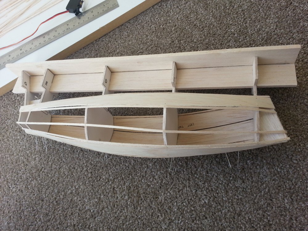
RacingSparrow Footy plans
A double diagonal design footy from RacingSparrow.

Logos & Sticker Sheet
Downloadable logos and an EPS file to be sent to a printer and printed out on navy blue cutout vinyl.
Common questions about the plans
What tools do i need to build a racingsparrow.
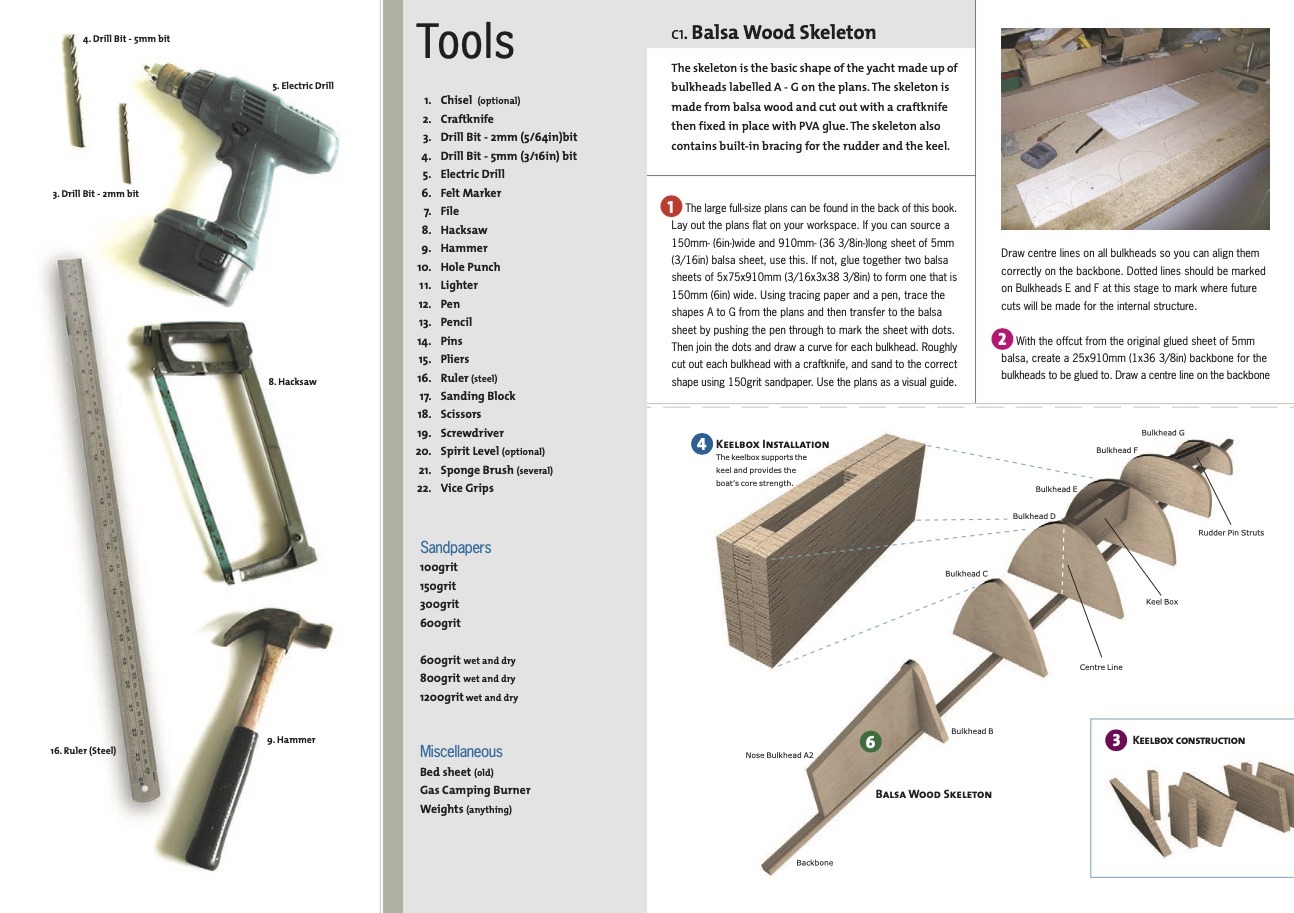
1. Chisel 2. Craft-knife 3. Drill Bit - 2mm (5/64in)bit 4. Drill Bit - 5mm (3/16in) bit 5. Electric Drill 6. Felt Marker 7. File 8. Hacksaw 9. Hammer 10. Hole Punch 11. Lighter 12. Pen 13. Pencil 14. Pins 15. Pliers 16. Ruler (steel) 17. Sanding Block 18. Scissors 19. Screwdriver 20. Spirit Level (optional) 21. Sponge Brush (several) 22. Vice Grips
Do I need the eBook to build this cool rc sailboat?
No you don't. The book is designed for the newcomer to model yacht building. The book does make it a much simpler process with every detail figured out and covered in the book. Seasoned builders can simply have a go with the free plans.
Are the plans really free?
Yes all the plans are free to download and use as you see fit. The most comprehensive plans are the RS750 A1 full size.
Are there CAD files or 3D files?
Yes there is a 3D dxf file inside a zip file that you can download for free and use how you want. Some people use this in CAD programs or in 3D modelling programmes to great effect. Look under Racing Sparrow 750 plans on this page. An STL file for 3D printing is in the pipelines. Email me if you want a copy.
While we think 3D printing is great, we believe old-skool strip planking balsa is a wonderfully simple way to make a very lightweight boat with excellent longitudinal strength and beauty.
Builders eBook
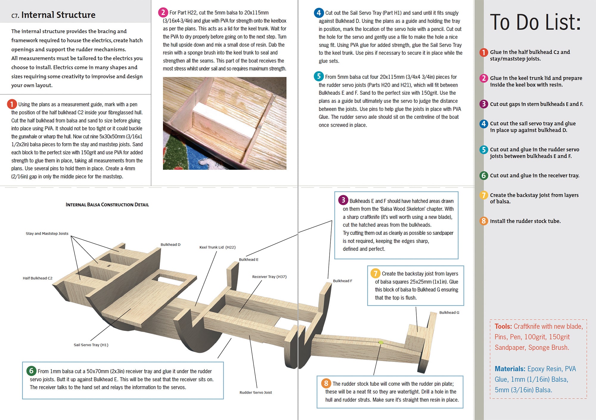
Dive into the world of boat building with our eBook. Discover the craft of hull planking, fibreglass strengthening, and lead keel ballast casting.
Master the art of electrics installation, spray painting, sail making, and tuning of sails. Download a sample today and embark on a rewarding journey of boat construction.
What the builders and sailors say:
Being a complete novice, I purchased your book a couple of years ago and built two racing sparrows. Building on this experience I then went on to build, from scratch, an IOM (Triple Crown design). I've since joined a local club and sail virtually every weekend. I would just like to thank you for your endeavours which have allowed me to enter a world I never thought was in my reach.
John Sterland, Australia
Coming upon your book, "Build your own Radio Controlled Yacht" in the Napier Public Library, I am hugely impressed. The combination of your superb photos and illustrations with your easy writing style make it a standout publication and I hope it does well for you.
Richard Spence, New Zealand
Thanks for an excellent design in your RG65. I trialled her again today in a solid 20 knots gusting higher. Even so in a steep chop and fingers off the rudder she drove upwind remarkably well, balanced perfectly. Very impressed that a model boat can handle that with a large rig. I found the book excellent. Ive built several big boats, plus a few skiffs and without that resource building such a good boat would have been impossible.
Mike Bennett
Look at all these cool boats folk have made at home
There is also a full gallery with a boat load of photos of Racing Sparrow's
Sparrow I found on the net, looks like an rs1500 , Internet
Feb 2, 2010

The woodwards Father & Son team on launch day. , New Zealand
Aug 1, 2007

Rod Patterson , Christchurch, New Zealand
May 4, 2012

Eric Rosenbaum - A fine fine model yacht , USA
May 4, 2009

Royal Declerk's cool Multi-Hull , Australia
Jun 11, 2015

Dear Bryn, I felt I had to tell you, my beautiful 75, "Jack Sparrow" got away from me due to a radio malfunction and sailed off into the distance across Port Phillip bay to be not heard of again, probably on its way to China?? so have made three land yachts for the grandchildren, sail them at Sandy Point ( Gippsland)
My latest model is a foiling catamaran based on the AC45 (another brilliant NZ design)(very sad to see NZ beaten in the cup) and so "Black Mamba" has evolved.
Yet to do sea trials but if it works as intended will be amazing. Best wishes from Royal Declerck.
Jerry Cashman's RS750 , Canberra, Australia
Nov 26, 2022

Hello! Here a couple of pix of my Sparrow. She’s been finished for a year or so now but the lockdowns has kept her out of the water largely.
She’s a beaut. Sails beautifully on just the lightest air. Thanks for the design!
Bill Cobb , Zurich
Aug 23, 2013

Hi Bryn, I built an RS1000 and had so much fun building and sailing it I decided to build a couple of RS750's for my grandchildren in Zurich. Bit of juggling to get them into a suitcase but the whole project worked well and the boys just love them. Bill Cobb. - what an awesome Grandad!(Bryn).
Jonathon Gillham , New Zealand
Oct 11, 2018

Martin Whittle, RS750 , UK
May 1, 2011

Eric Rosenbaum , USA
Feb 2, 2009

- Motorcycles
- Car of the Month
- Destinations
- Men’s Fashion
- Watch Collector
- Art & Collectibles
- Vacation Homes
- Celebrity Homes
- New Construction
- Home Design
- Electronics
- Fine Dining
- Aston Martin
- Les Marquables de Martell
- Mira Villas
- Panther National
- Reynolds Lake Oconee
- Wynn Las Vegas
- 672 Wine Club
- Sports & Leisure
- Health & Wellness
- Best of the Best
- The Ultimate Gift Guide
This New 144-Foot Superyacht Wants to Be the SUV of the High Seas
Antonini navi's new sport utility yacht (suy) can take you 4,000 nautical miles in luxury., rachel cormack.
Digital Editor
Rachel Cormack's Most Recent Stories
This new 80-foot explorer catamaran has a roof that doubles as a helipad.
- Paul McCartney Is Auctioning Off the Iconic Beatles Boots He Wore at the 2012 London Olympics
- This Luxe Train Ride Lets You Take In Vietnam’s Lush Countryside Over Afternoon Tea
- Share This Article

Antonini Navi appears to have created the Range Rover of the high seas.
Related Stories
- Jaguar’s Next Wave of EVs Will Launch With a 575 HP Grand Tourer
- Ferrari’s Signature Naturally Aspirated V-12 Engine Isn’t Going Anywhere—for Now

The yacht can be fully customized inside and out by the owner, naturally. The proposed interior layout sees the main and upper deck connected via a raised deck with a short staircase. An owner’s suite of roughly 600 square feet occupies pride of place on the main deck, while four en suite guest cabins are located on the lower deck.
Outside lies a 430-square-foot veranda with an alfresco dining space that is protected from the elements by the raised deck. Further aft, the sprawling beach club is centered around a striking transom Jacuzzi that overlooks the sea below. Nearby sits a sizable transversal tender garage large enough to store a 23-foot RIB and plenty of water toys. Up top, the sundeck is outfitted with a bar, dining table, sun pads, and another Jacuzzi.
The SUY 135 should run as well as your Rangie, too. The newcomer has a range of 4,000 nautical miles at a cruising speed of 10 knots and can reach 16 knots at full tilt. It is also equipped with zero-speed stabilizers to ensure comfort on the water.
“Exactly like an SUV in the automotive world, the SUY offers the opportunity to experience the vessel with no limits”, Manna said in a statement. “The idea was created to allow the owner and his guests to enjoy their yacht at 360 degrees, being able to have toys, amenities, tenders, and any other means suitable for the many sporting and recreational activities that the sea and its places can offer.”
Rachel Cormack is a digital editor at Robb Report. She cut her teeth writing for HuffPost, Concrete Playground, and several other online publications in Australia, before moving to New York at the…
Read More On:
More marine.

This Sleek New 55-Foot Carbon-Fiber Yacht Looks Like a Spaceship for the High Seas

Will Smith, Tom Brady And More Celebs Are Team Owners in a New Electric-Boat League

This 180-Foot Trinity Superyacht Stars in the Newest Season of ‘Below Deck Mediterranean’

Culinary Masters 2024
MAY 17 - 19 Join us for extraordinary meals from the nation’s brightest culinary minds.
Give the Gift of Luxury
Latest Galleries in Marine

The 10 Best Explorer Yachts for High-Seas Adventures

Mirrari Yacht in Photos
More from our brands, the 7 best heatless curlers for effortless waves overnight, nfl beats gruden in nevada appeal as dispute goes to arbitration, bruce springsteen documentary about e street band world tour set at disney+ and hulu, new york may auctions get off to a slow start as pricey bacon misfires during sotheby’s $267.3 m. sale, the best yoga mats for any practice, according to instructors.

COMMENTS
Stiletto! A 1/4 scale R/C model of my America's Cup winning US 203. It has many of the same features found on full size land yachts. I Including a double-tapered wing mast and weight-tuned suspension. Stiletto is not a "sailboat on wheels", rather, it is a true land yacht model. With a top speed of over 30 MPH, you won't find a better kit anywhere.
The Stealth series of Model land Yachts unltd. was added in early 2000. Popular demand, mainly from the modeler who has no time, encouraged me to develop a model that comes with all prebuilt assemblies. The Stealth line will be expanded to include the Stealth "M" (smaller than Class 1) and the Stealth S3, class 3 (larger) kit.
With their high profile sails and wing masts the LS series of model landsailers point higher and go faster than any RC sailboat. They can sail on concrete, blacktop, hard sand, dirt or any other smooth surface. The smoother the field, the faster they go. The LS-3 "Ugly Duck" is a simple, efficient design that conforms to IRCSSA class II ...
Meet Stiletto--a 1/4 scale R/C model of my America's Land sailing Cup winner: US 203. It has many of the same features found on full size land yachts, including a double-tapered wing mast, weight-tuned suspension, variable rake mast, etc. Unlike the few other available models, it is not a "sailboat on wheels". Rather, it is a true Model Land Yacht.
When used on inline skates or skate boards you can notice great differences in bearing performance because each set of bearings is supporting 20-40 pounds. On a model landsailer each set of bearings supports about 1-2 pounds. This small load makes the advantages of "better" bearings much smaller.
Description: The MIA Trike-a-Sail™ Pantera RC Land Yacht, while sophisticated in design, is an high performance, easy to run and highly durable RC Land Yacht or Land Sailer, also know as Carro Vela, or Char-a-voile, operated by 2-Channel radio control. Front Steering and Sail. Optional Throtle for Powered control requires a 3rd channel.
RC model land yacht project suitable for schools.https://www.youtube.com/watch?v=UdWBAMP_CxE
The first step in designing this land yacht was assembling all the required RC gear. This really dictates the layout and physical size of your land yachts 'body' For a functional land yacht you only need a very basic RC setup: 2chanel transmitter & receiver; 1x battery pack; 1x servo switch (on off switch) 1x steering servo (i used a 17g servo)
Browse Airstream LAND YACHT RVs for sale on RvTrader.com. View our entire inventory of New Or Used Airstream RVs. RvTrader.com always has the largest selection of New Or Used RVs for sale anywhere. (1) AIRSTREAM 28FB. (2) AIRSTREAM 30. (2) AIRSTREAM 30SLD. (1) AIRSTREAM 31.
Model Land Yachts, Unlimited. 94 likes. Robert Weber ,owner of Model land yachts, is producing these model kits for over 25 years.Check it out at www.modellandyachts.com Model Land Yachts, Unlimited
Yes, just kits here. He makes the "hull" out of fiberglass now. The older ones were vacuum formed plastic. I have two of his original S2 land sailors here if your interested. One is complete and the other needs a sail. If your interested, shoot me a PM. SJ. Jul 14, 2015, 04:02 PM.
Price. $25.00. More info . Stiletto. Click to enlarge image (s) Model Land Sailing is Like Flying a Boat on Wheels. Stiletto, the first of the series. Comes with two appropriate servos and 3 wire on/off switch installed. Of course you can add all the electronics to the kit.
Mine were about 80 cm long with a 90 cm mast set with a 20 degree angle set back. I used a regular steering servo to control the sail but a "real" sail servo would have been better. RC Sailboats - RC Land Yacht plans - I have been building scratchbuilt foamy planes for years but I am always fighting the wind so I thought it about time to build ...
To steer the land yacht, you push on the right pedal to turn left and on the left pedal to turn right, with some land yachts having the option to hand steer instead. Types of Kart - The four main types of land yacht are the 'Standart,' the standard model, the 'Mini Yacht' a smaller, more beginner-friendly version of this vehicle, the ...
Semi scale land yacht, length 900mm and cross width 560mm. Uses standard RX and servos for steering and sail control. ... Home Model Boat Plans Model Boat Builders Plans Unconventional Designs Pacer Land Yacht (Model Plan) Pacer Land Yacht (Model Plan) £11.50 each. Approx: €11.11 / US$12.17 Tax Free. In stock. Marine Modelling International ...
We created a unique exterior design with sleek, unbroken surface with the paintwork as beautiful as possible. We hide all of the protruding parts, the hinges, handles and windows. As a trademark, Dembell red colored stripes run on the sides of our. luxury motorhome. , which comes with a special color-matched, Dembell edition Vespa and Smart.
The Land Yacht is available in two interior colors, Mocha (seen Here) and Polar (shown at top). "The Land Yacht is kind of an ode to the olden days of Wally (Byam) with his dream and passion of travel, adventure and sailing," explained Melton. "This model represents the most luxurious Airstream model, with fine detailing and design ...
HK-GT2 2.4 Ghz Digital Proportional Radio Control System: Price $ 90. 00 More info
Yes there is a 3D dxf file inside a zip file that you can download for free and use how you want. Some people use this in CAD programs or in 3D modelling programmes to great effect. Look under Racing Sparrow 750 plans on this page. An STL file for 3D printing is in the pipelines. Email me if you want a copy.
A land yacht is an informal category of large automobiles. While full-size cars are manufactured worldwide to this day, the term is most often used to describe the full-size cars of American origin between 1960 and 1976.. Alongside full-size and luxury four-door sedans, the land yacht term applied to multiple body styles, including two-door notchback sedans, personal luxury coupé ...
Available Colors. Airstream RVs. Airstream RV started in 1929 when Wally Byam put a tent on the top of a Model T chassis. The inspiration was due to the love of camping, but not sleeping on the ground. Since the first prototype didn't work well in the rain, Byam replaced it with a teardrop shaped shelter on top and added a stove and ice chest.
Antonini Navi just unveiled the first model in a new line of Sport Utility Yachts. The SUY 135 offers impressive seakeeping, comfort, and luxury.
The S3 design of the wing mast /sail combination is unique. The frame can be split in half and all this almost 6 foot tall Model will fit into a 4 x 4 x 48" box, which allows me to keep the shipping costs low even into foreign countries. Extensive testing also showed that the typical hard foam wheels used in the smaller models are not good enough.