Hotel with the best pool complex at Disney World: Review of Disney's Yacht Club Resort

Update: Some offers mentioned below are no longer available. View the current offers here .
When you think of a Florida theme park hotel, I'd bet you probably don't think of deep, rich colors, hardwoods and a refined turn-of-the-century, New England-style nautical-themed resort.
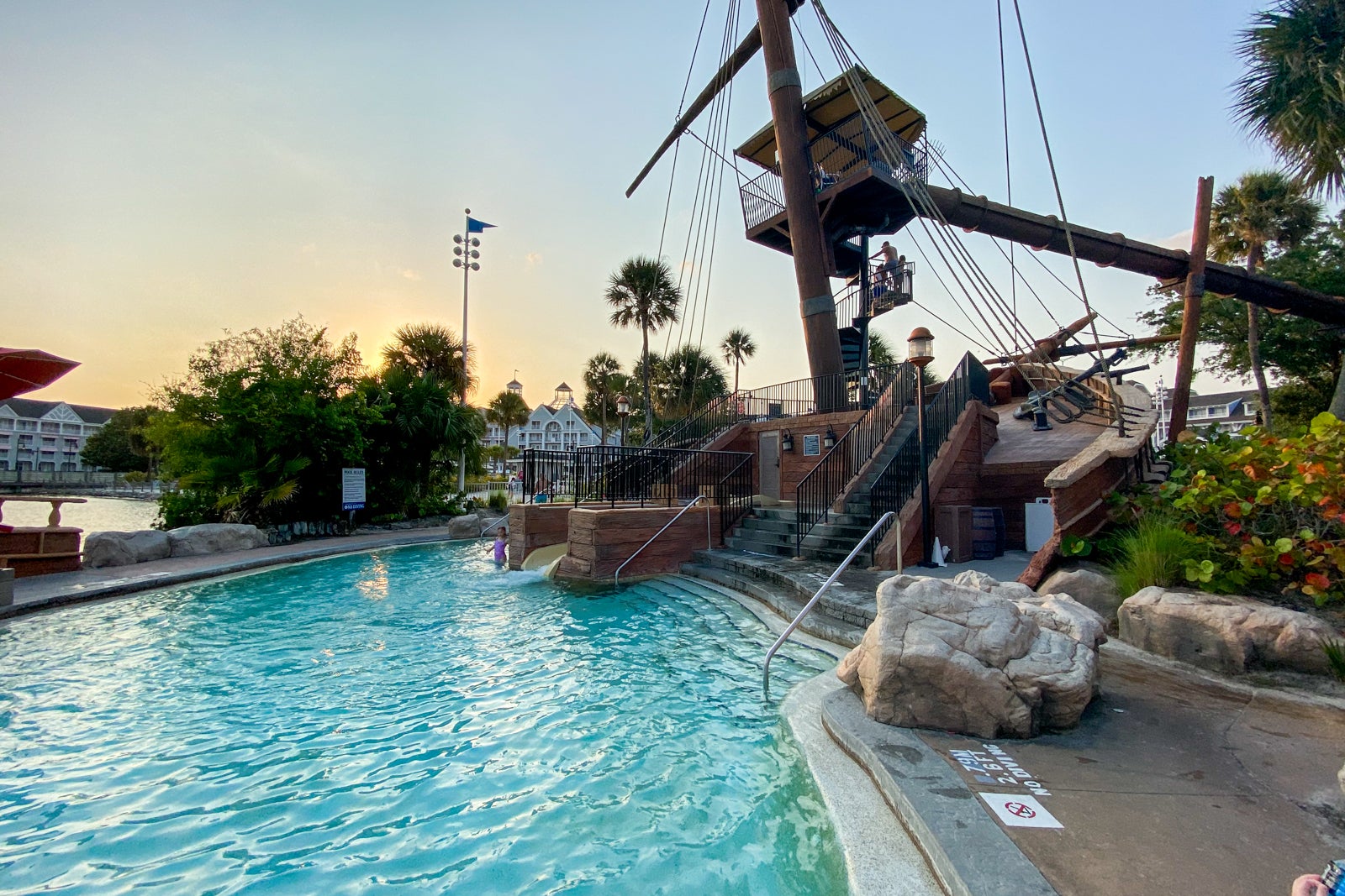
And when you think of a hotel pool, you likely don't conjure up images of a 3-acre waterpark complete with a life-size shipwreck replica that is home to a long, twisting, turning waterslide.
But all this, and actually a lot more, is precisely what you'll find at what has to be one of the best hotels at Disney World , Disney's Yacht Club Resort. In fact, when we picked this resort for a short Florida getaway, we actually considered not spending any days in the Disney theme parks to go along with it. We amended that plan for one day at Epcot, but it wouldn't be unreasonable to do an entire vacation here without getting on a single ride. In this case, the resort could be the destination.
For more TPG news delivered each morning to your inbox, sign up for our daily newsletter .
Disney's Yacht Club (1990) opened in the same era of rapid Disney World development as Disney's Caribbean Beach Resort (1988), and both share a type of ocean theme. However, the two couldn't be more different from one another. With just over 600 rooms (compared to more than 1,500 at Caribbean Beach), this deluxe Disney resort offers guests a vacation within a vacation both in terms of comfort and amenities.
After a recent stay at the property, it was all I could do to not add another night when the time to check out unfortunately arrived. And while not everything is postcard-perfect at this Disney resort at the moment, I promised myself (and my kids) we'd be back. It's that special.
Let's start with some bad news: Disney's Yacht Club is often expensive.
This is one of Disney's deluxe resorts and there is no Disney Vacation Club wing of this hotel. This means you can't rent DVC points to potentially book a room for less the way you can at places such as Polynesian Village Resort. (Note that you can do this at the neighboring Beach Club Resort.)
If you can snag a room during a sale or with a solid discount, you can probably get the rate down to $350-$400 per night, but it's unlikely to go much lower. It's common for rooms here to go for $500 and up, especially once standard rooms are sold out and you need to pay even more for a water view, which is precisely what I had to do. The view itself is (in my mind) not actually worth an upcharge, but sometimes that's all that's available.
While I booked during a 30% off sale, my water-view room at the Yacht Club still came to just over $500 per night. There are some ways to use points for Disney World vacations , such as using miles from the Capital One Venture Rewards Credit Card to offset the expense at a 1 cent = 1 mile valuation , but there's no way to get outsize value for your credit card points at Disney properties.
If you do decide to book a Disney resort like this one, it can make sense to go through a Disney Vacation Planner as that doesn't add to your cost and they do a great job staying on the lookout for sales and discounts and keeping track of all those ever-changing components of a trip to Disney World.
Related: How much does a trip to Disney World cost?
FOR NO-COST ASSISTANCE WITH PLANNING AND BOOKING YOUR NEXT DISNEY VACATION, CHECK OUT TPG'S DISNEY BOOKING PARTNER, MOUSE COUNSELORS .
No doubt it sounds a touch insane to spend $500 for a theme park-adjacent hotel room, but the location is one reason why Disney's Yacht Club commands that rate (and often sells out).
This hotel is just a 5-10 minute walk from the World Showcase entrance of Epcot. It is also within walking distance of Disney's Hollywood Studios, or you can hop on a boat to take you there since that walk is a bit longer.
Being so close to Epcot also means that the Skyliner stop at Epcot is within very easy reach, opening up even more Disney locations such as the Riviera Resort , Caribbean Beach Resort and more.
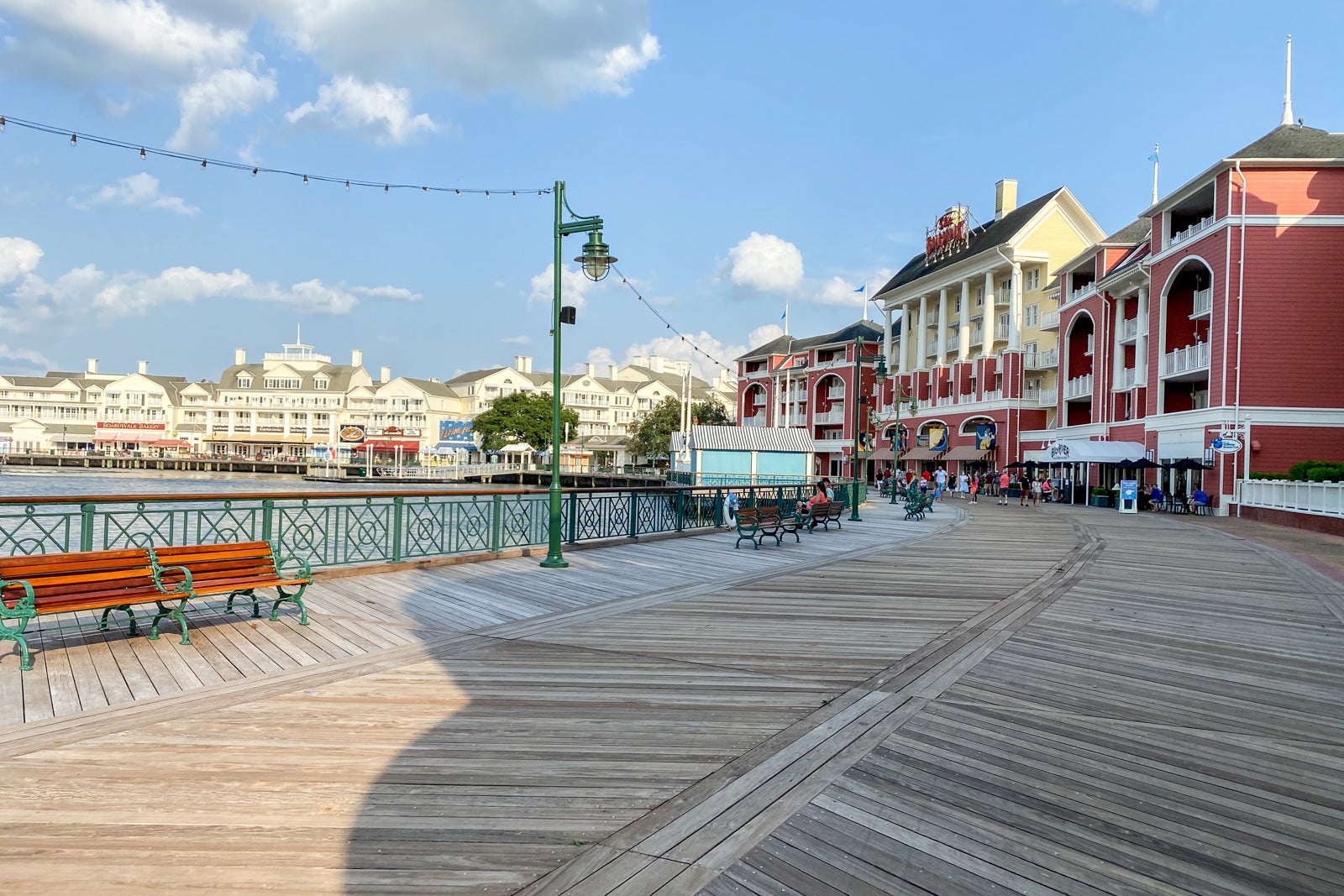
Yacht Club is also an incredibly short stroll away from the BoardWalk, which is home to even more shops and restaurants.
I'm happy to save money and stay off Disney property on the first night of the trip, or for trips when we aren't going for an all-in Disney family vacation. But when we do go all-in on Disney World, I want to be in the "Disney bubble." Staying at Yacht Club puts you in the heart of the Disney bubble, well-cushioned in your own deluxe nautical-themed space, but just an arm's reach from lots of great Disney dining and entertainment options.
Related: Guide to visiting Walt Disney World
We arrived at Disney's Yacht Club in the early afternoon, after starting the vacation off with a character brunch at Topolino's Terrace at the top of the nearby Disney Riviera Resort . (Which I highly recommend you add to your to-do list if you love characters and can snag a reservation.)
Since we arrived a few hours before official check-in time, I didn't have high hopes our room would be ready, given the era of pandemic precautions, but that became the first pleasant surprise of the trip when Room 2077 was ready and waiting for us several hours early.
Check-in is also where we were informed that while room service has returned as an option for breakfast and dinner, regular housekeeping had not yet returned to Disney resorts . Towels and trash would be attended to every other day. For our two-night stay, that meant there would be no formal housekeeping services, though we could ask for more towels and such.
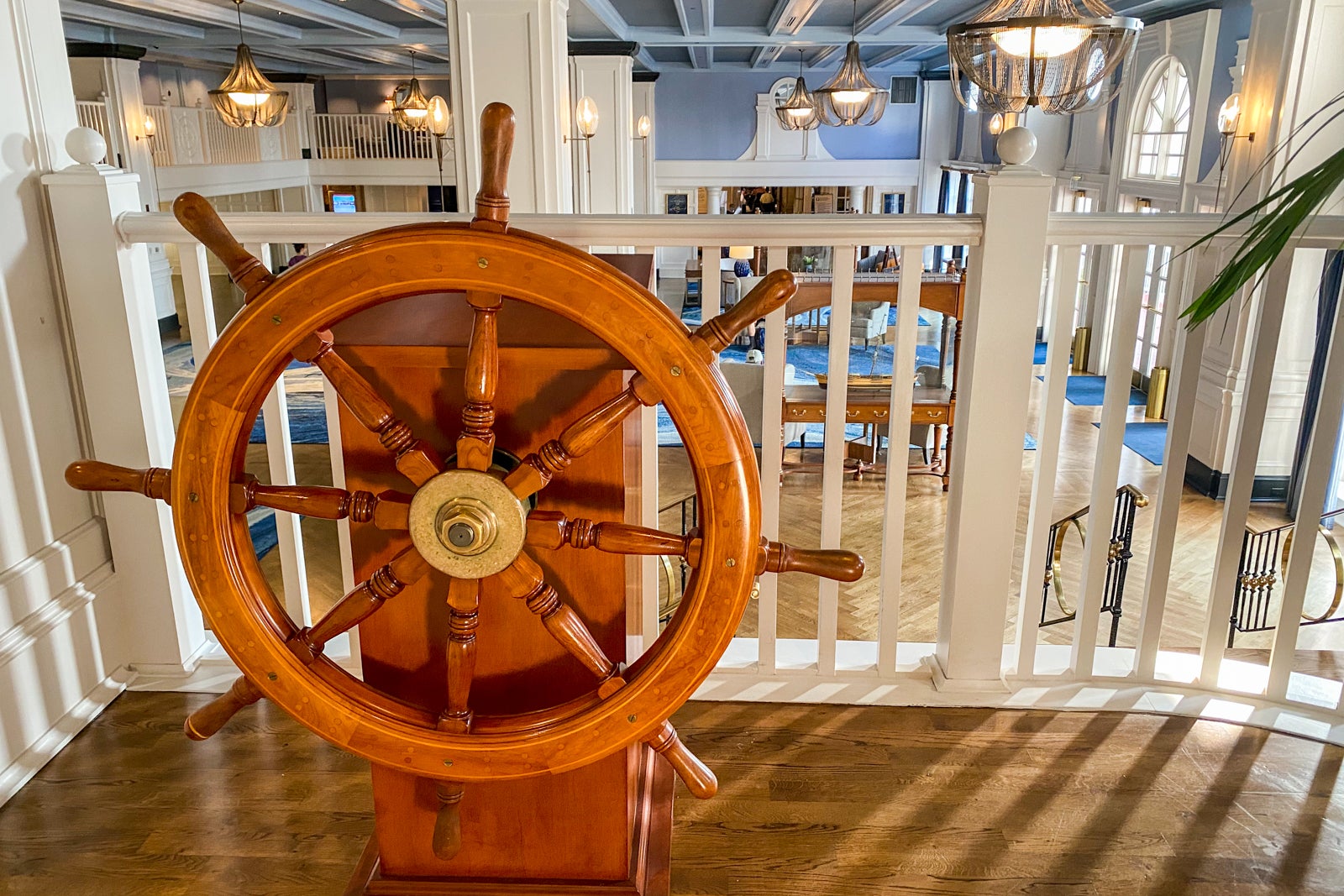
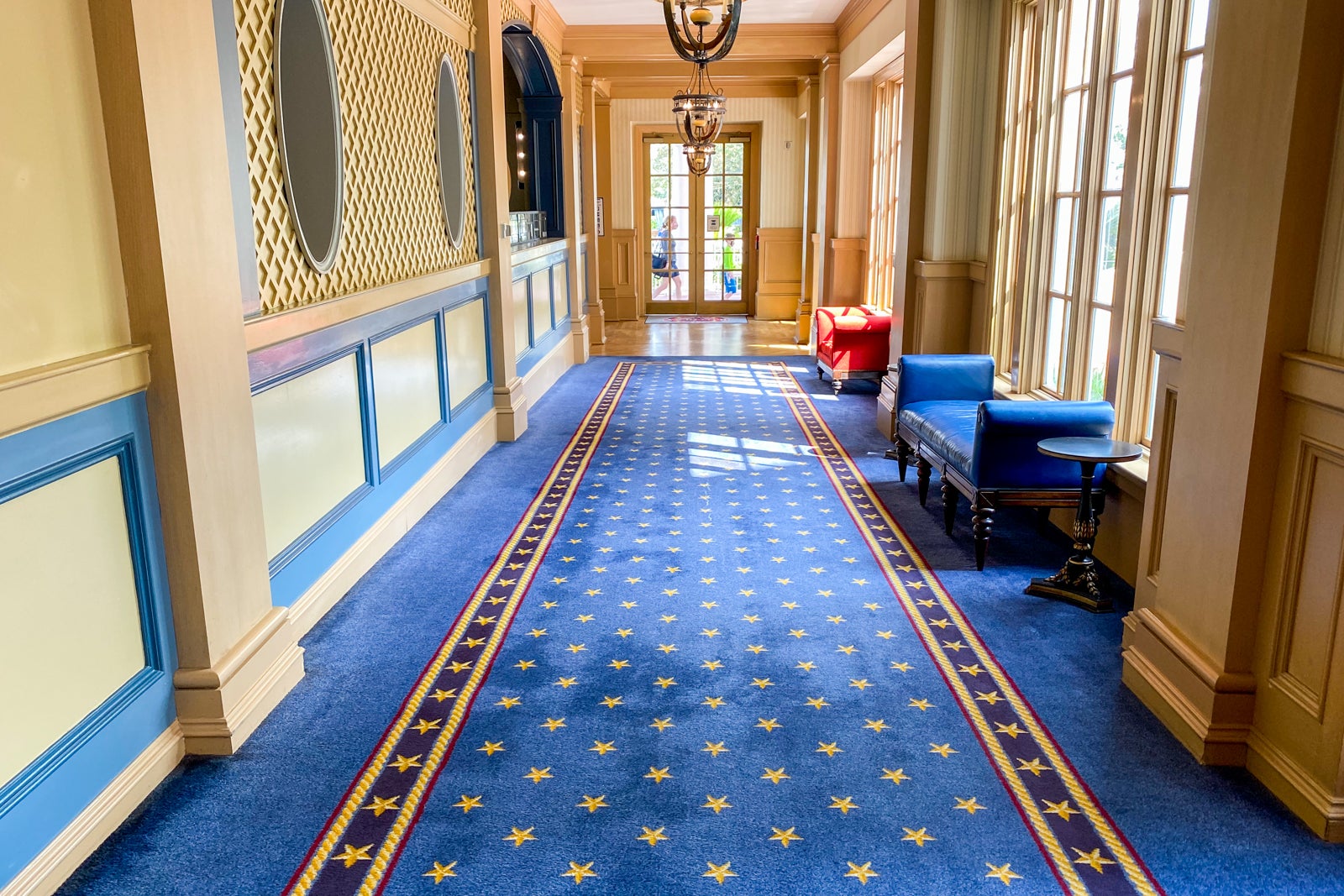
If you are able to manage stairs, you can easily access the second level of the resort — where we stayed — via the lobby without using the elevators.
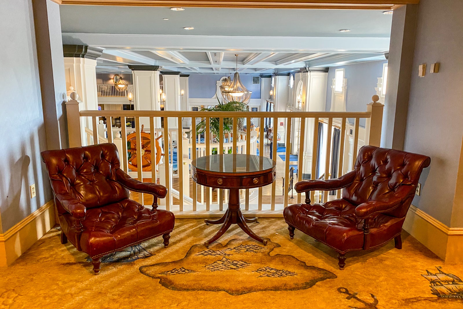
In fact, heading up the lobby stairs reveals some fun touches, such as a ship's wheel, among other themed decor.
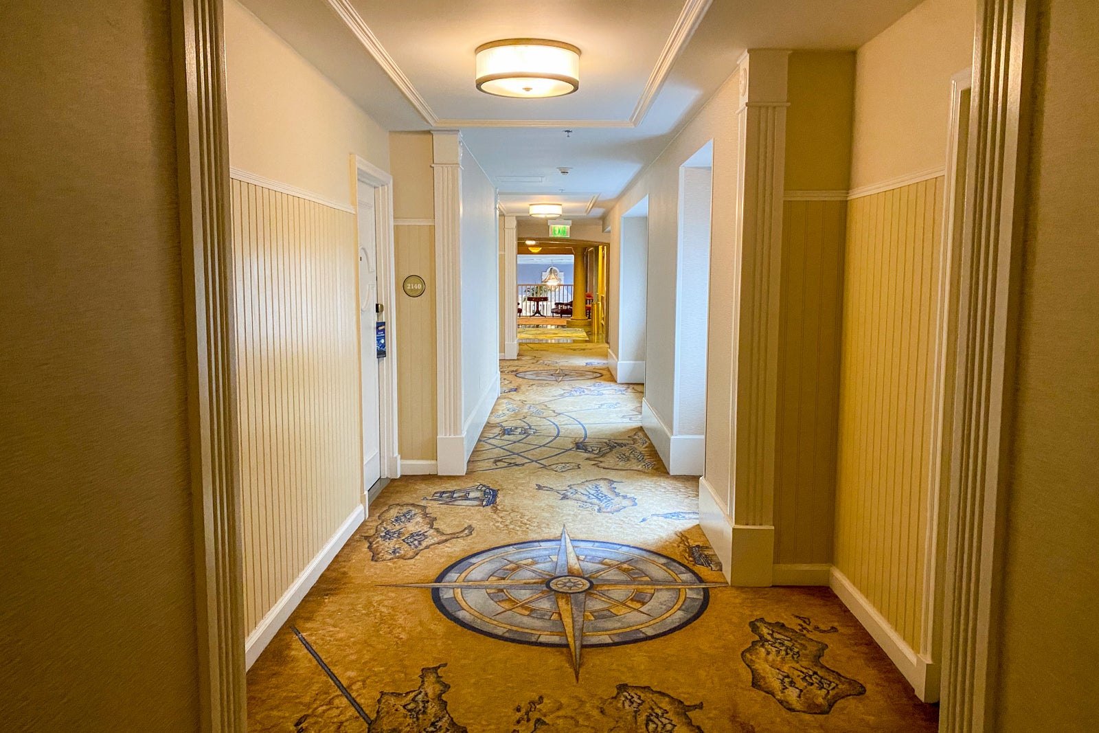
Our room was a bit of a walk down several hallways, so if that's an issue, ask for a room closer to the lobby if available.
Inside a room at Disney's Yacht Club, you aren't going to find bright colors, Disney characters or loud decor. If that's what you want, I recommend Disney's Art of Animation , which has plenty of color and characters.
Yacht Club was renovated in recent years to appeal not only to traditional Disney vacationers but also to conventiongoers who frequently stay at the resort during normal times. And in this case, everyone won with a redesign that maintained the overall theme but upgraded the offerings.
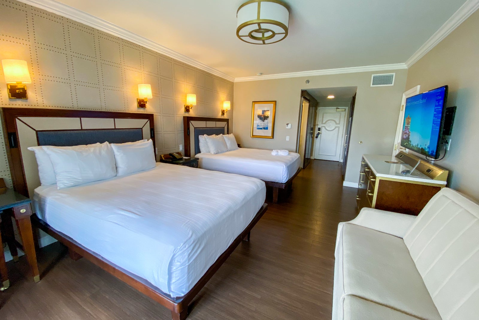
The rooms still carry out the resort's high-end nautical theme, but in a way that is elegant and more refined than the previous 1990s-era version.
Like with other Disney resort upgrades, the beds are now raised and the floors are now hard instead of carpet. As Disney renovated rooms across its properties, this has been the standard it is changing to.
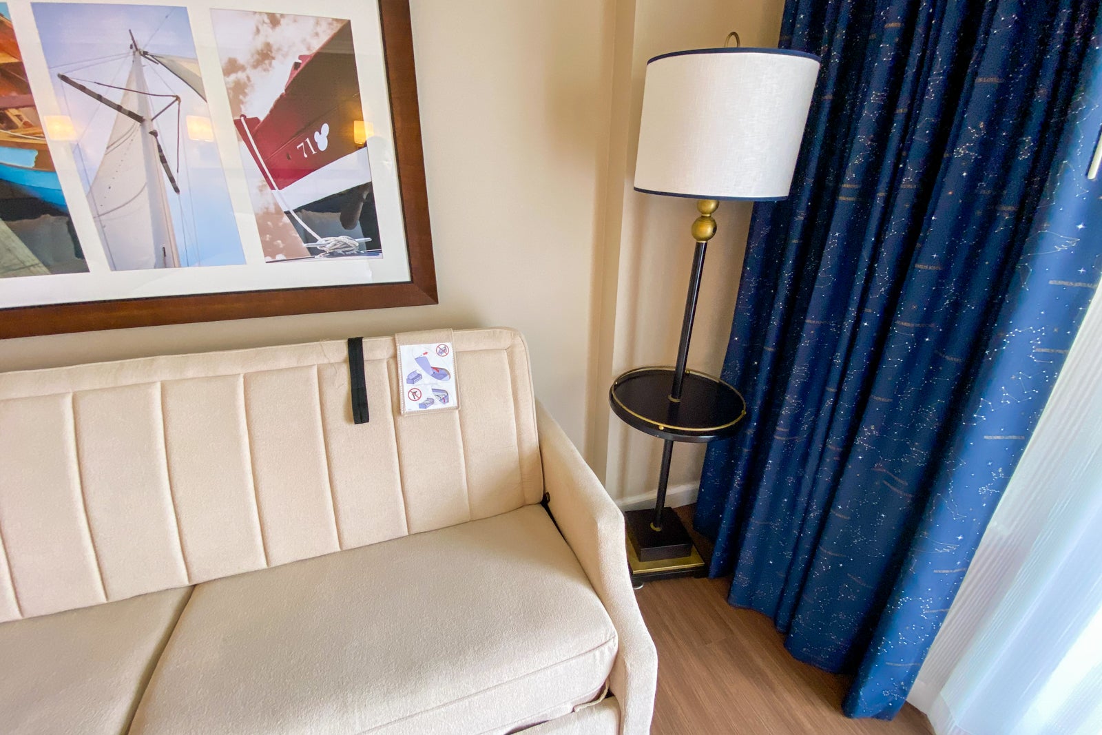
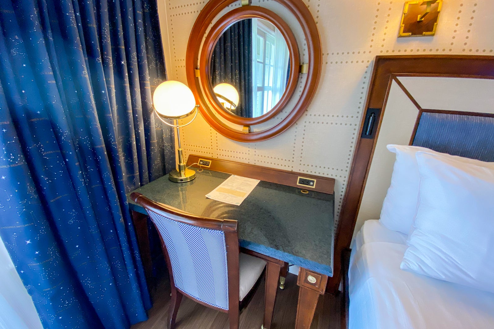
There's a pullout sofa that can be used as a sleeper and a small writing desk.
Most notably, there were outlets everywhere. We travel with a lot of things that need charging and we didn't come close to using them all up. Some furnishings may be made to look like turn-of-the-century New England, but they are loaded with modern-day power.
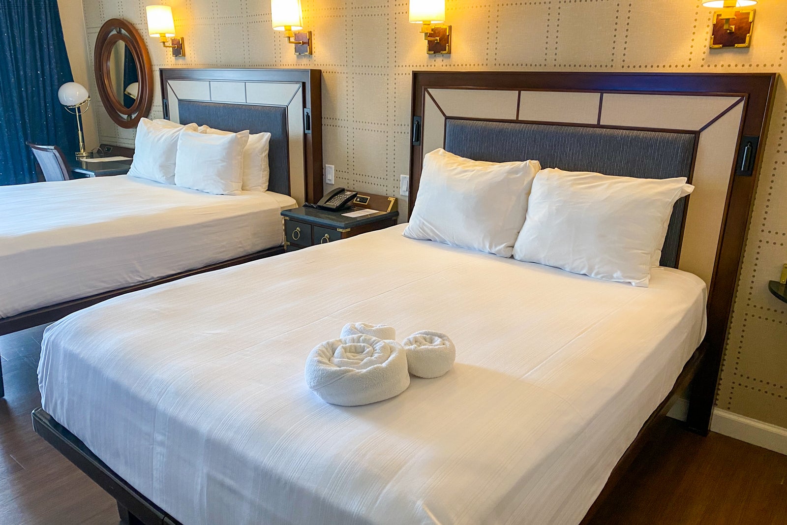
The two queen beds were perfect for a good night's rest after a busy day at Disney.
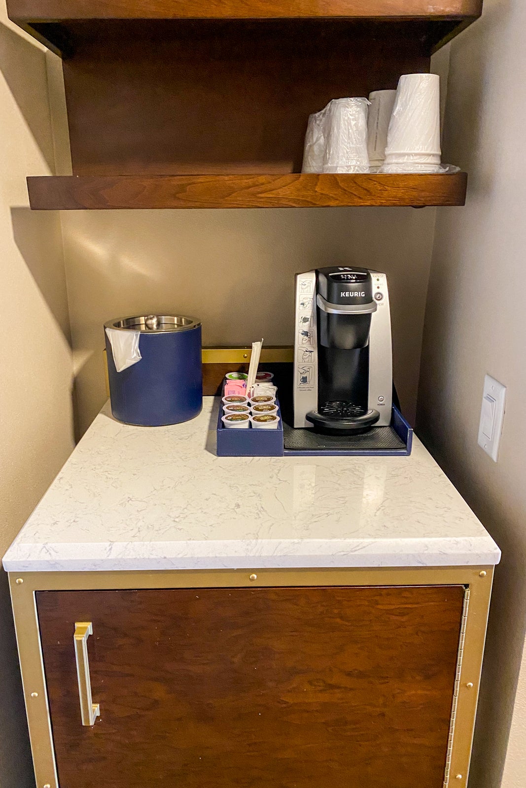
In the room, you'll also find a minifridge and Keurig.
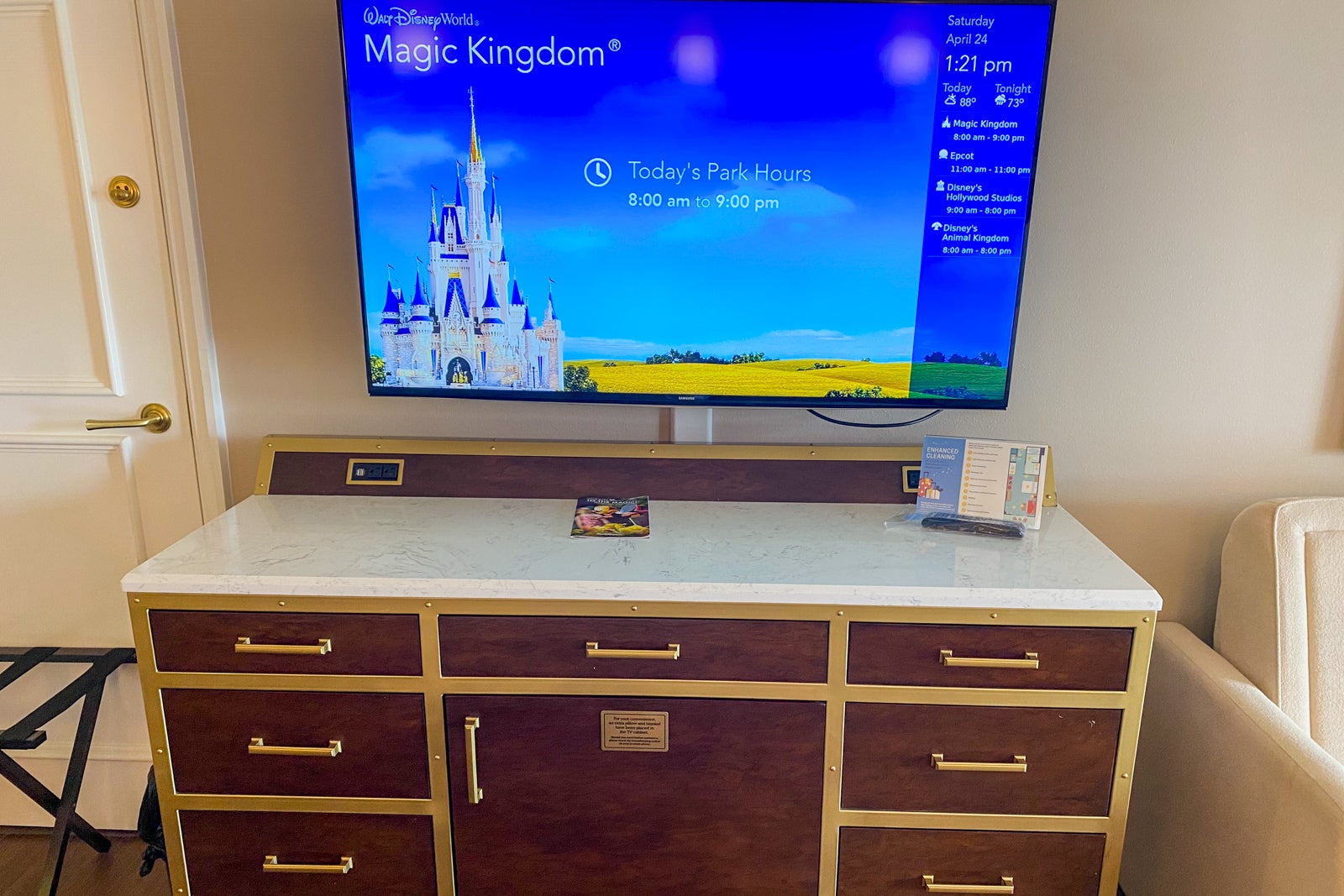
We were impressed with the amount of storage the room had in the form of shelves, racks, cubbies and drawers. We were able to stay far more organized than normal with a family's worth of stuff, thanks to the storage options.
There was a balcony with two chairs that overlooked a well-manicured green lawn and technically some water. Remember, this was a pricier water-view room after all.
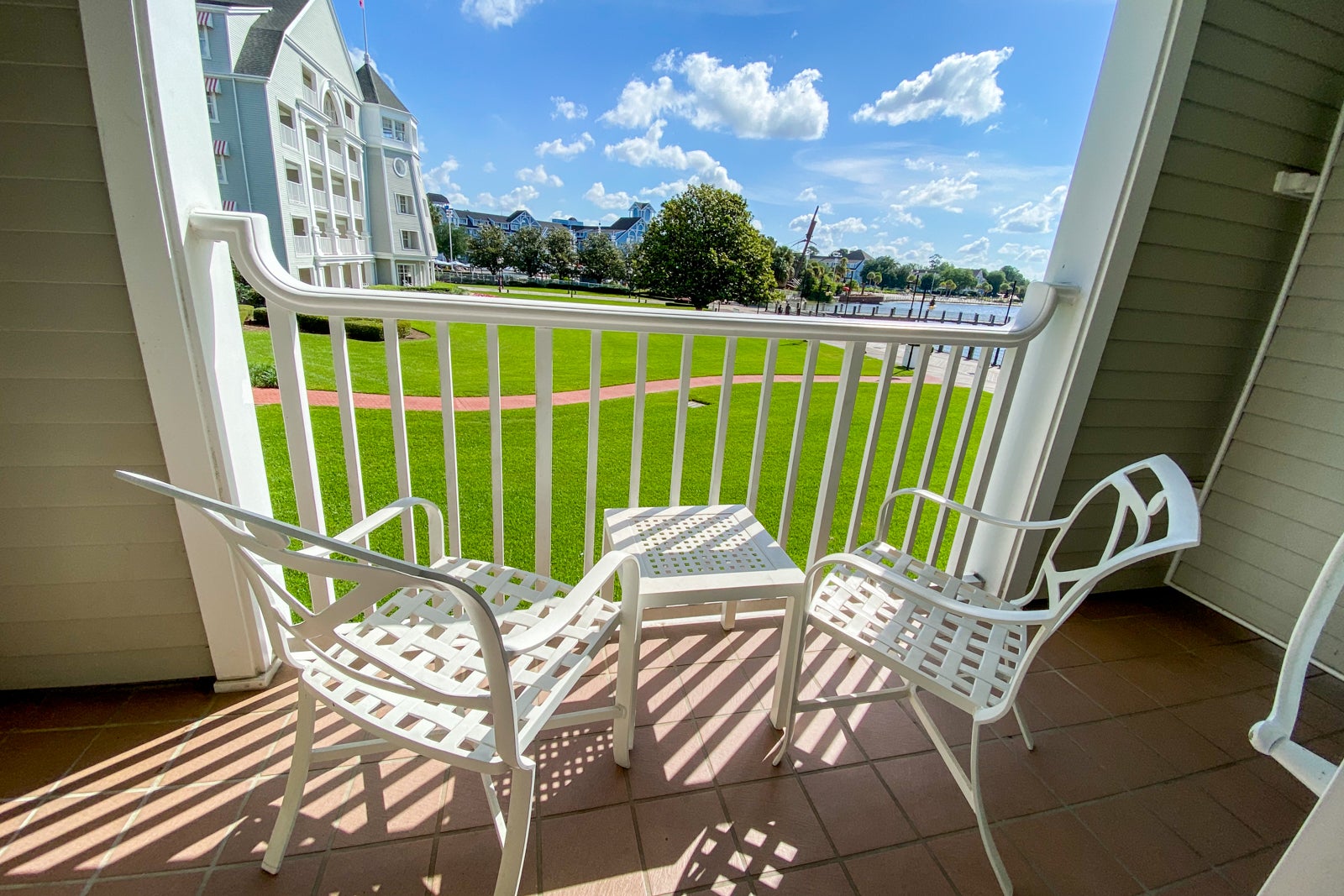
I adored the drapes, both because they did a great job keeping light out in the morning but also because they were adorable and perfect for the room, featuring constellations.
Like at many other similar Disney resorts, the bathroom had a vanity with two sinks located in a cubby between the main room and the bathroom, so it could be used while someone was in the shower.
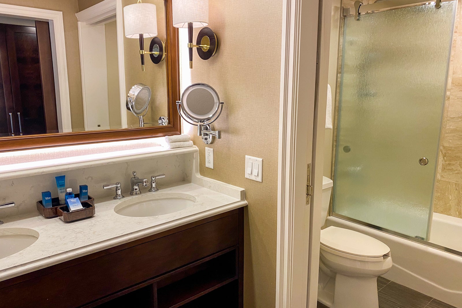
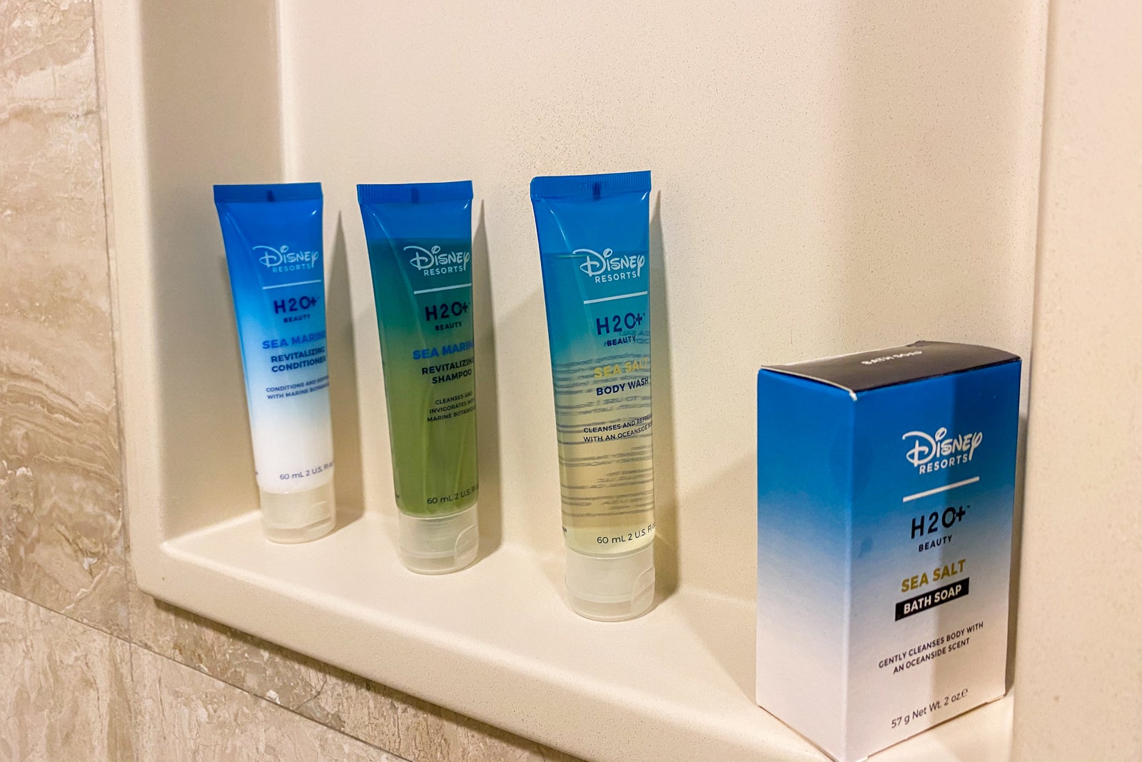
The bathroom area had a sliding door for both the room itself and the tub/shower combo. There were plenty of Disney H2O+ bath products in the shower and bathroom area.
We found the room incredibly nice, but do know that it doesn't take much to hear what's going on in the hallway or other rooms around you. If you like total silence, you'll be well-served to pack some earplugs and a white noise app to go along with your Mickey ears.
Related: Why you need more than just a ticket to get into Disney World this summer
The Yacht Club room is plenty comfortable, but that's probably not why you stay at Disney's Yacht Club — it's certainly not why we paid what we did to stay here.

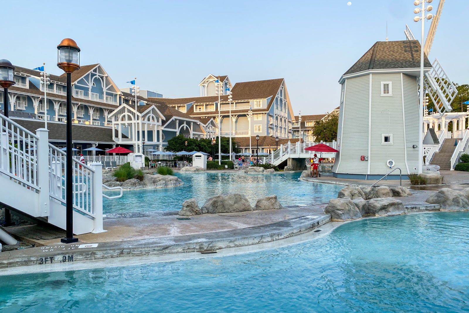
Stormalong Bay pool complex
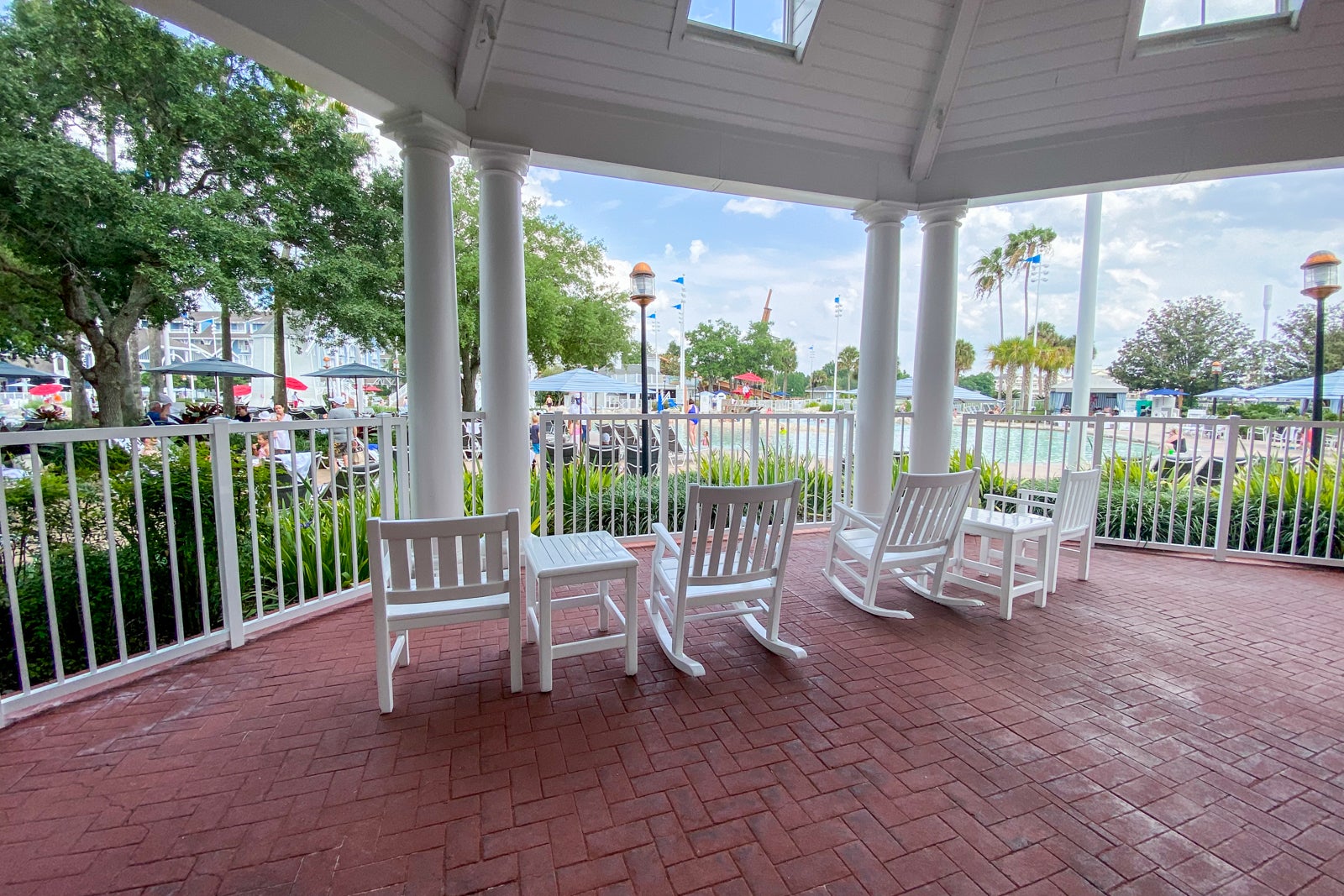
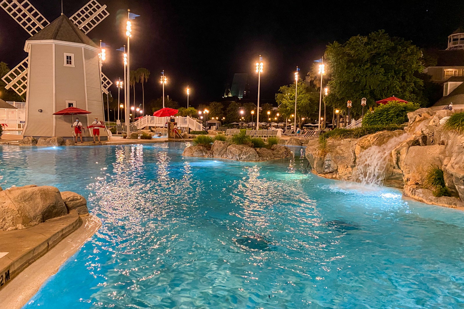
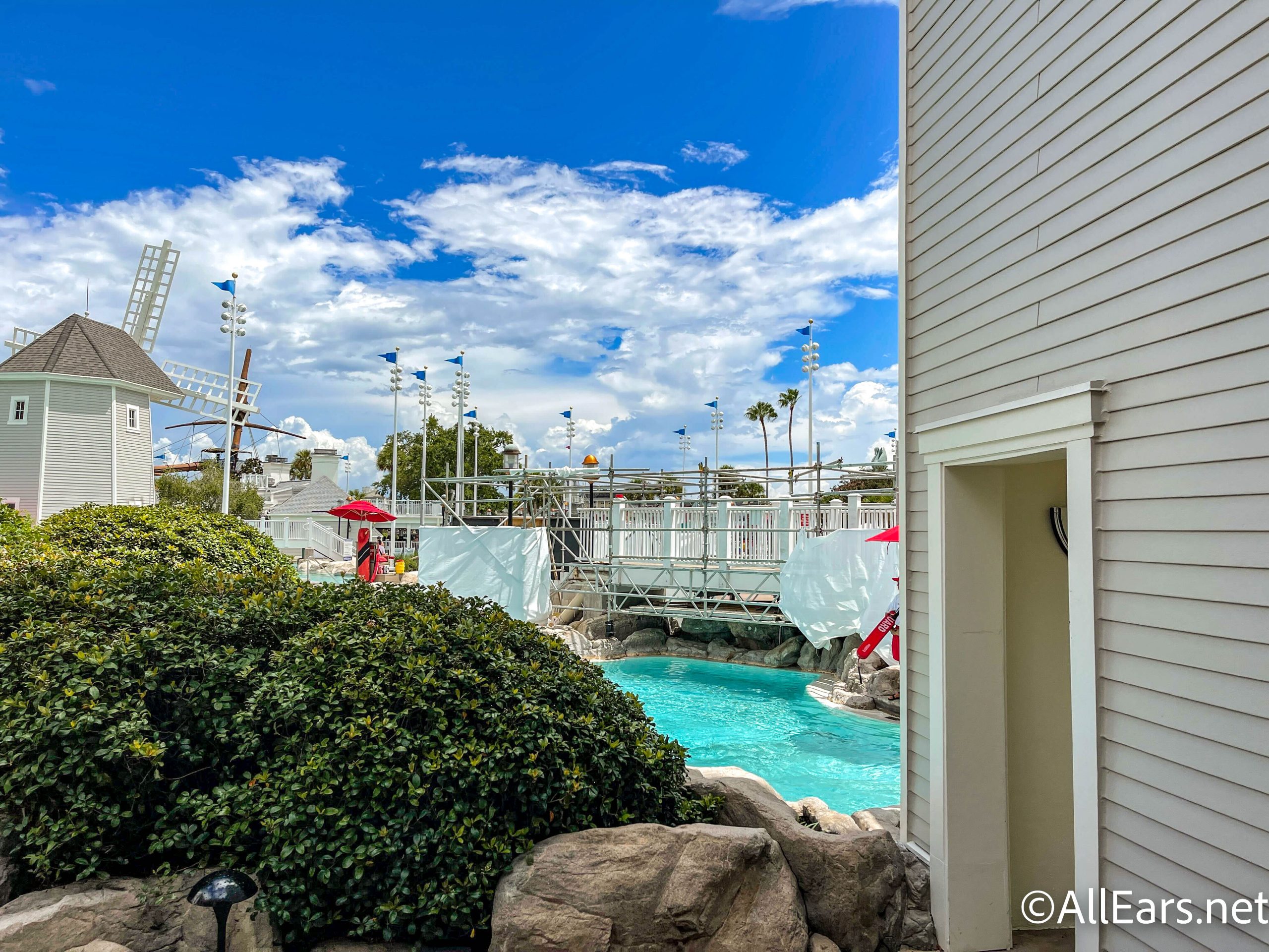
What makes this resort so special is the 3-acre pool complex shared with the neighboring Disney Beach Club Resort.
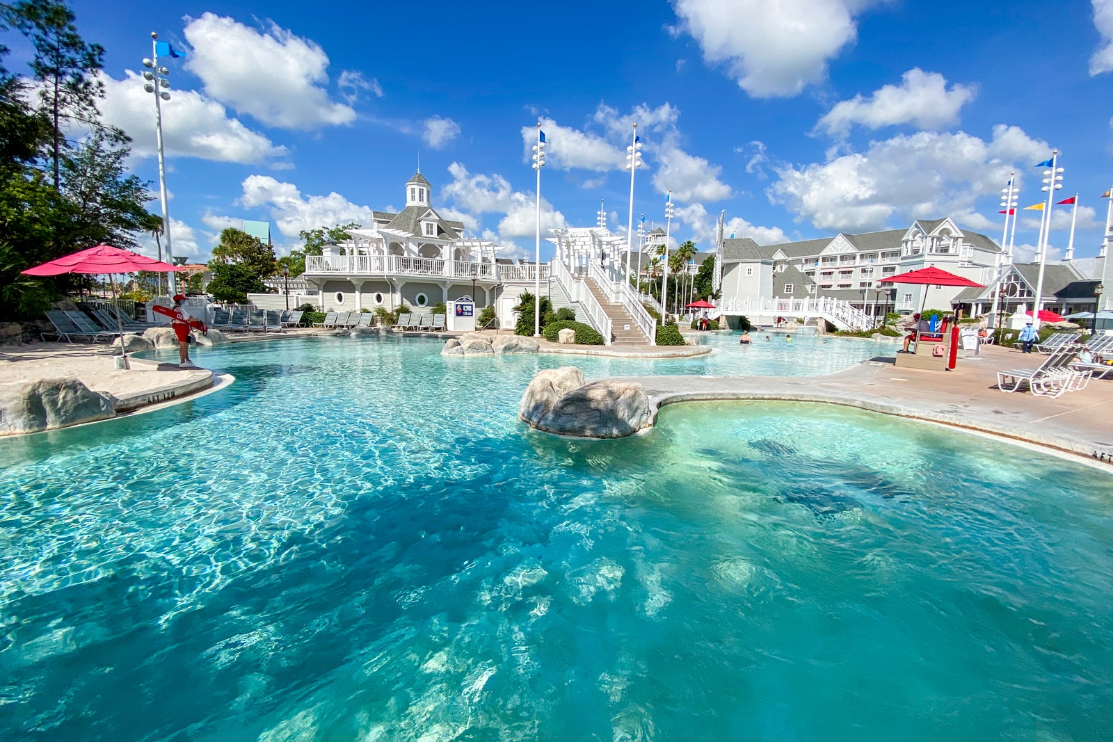
Dubbed Stormalong Bay, this pool complex has everything from a 230-foot waterslide to a lazy river, whirlpool, shallow splash area, toddler slide, hot tubs and more. It even has a sandy bottom in some of the areas, which feels so much nicer on your tired Disney feet than a hard surface.
This pool area is almost a mini-waterpark and certainly worthy of planning some time in your schedule just to enjoy it. Right now, it can get busy to the point where there is no way to get in during peak times.
However, we had a blast also going late at night after the parks closed, when there were very few people in the pool at all. While the hours can vary, it was open from 10 a.m. to 11 p.m. during our stay.
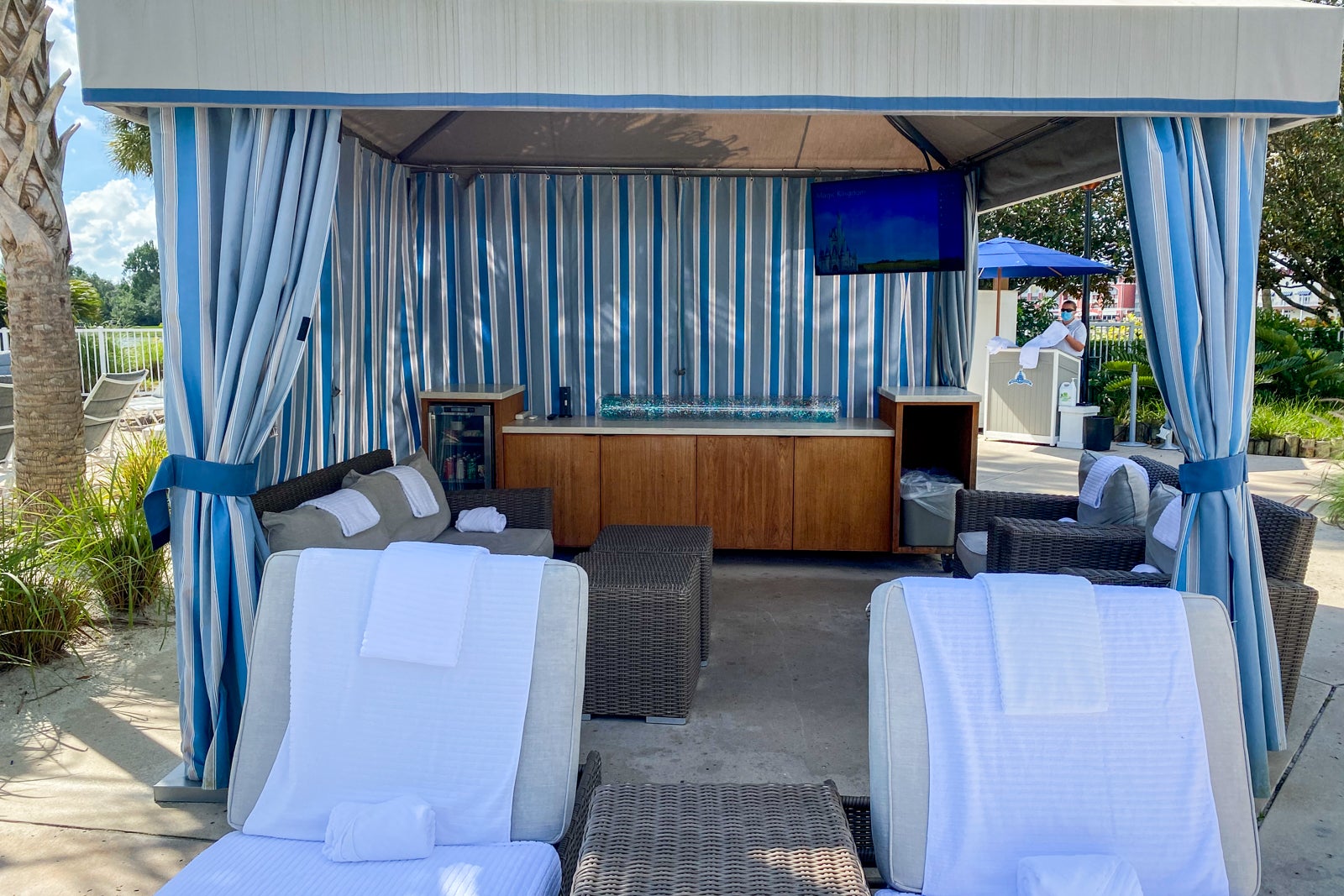
There are four cabanas at the pool you can book if you want extra space and service, but you need to reserve well in advance if you want those because they go quickly.
Getting into the pool requires verification you are a resort guest and you're then assigned the colored wristband of the day to wear. There's plenty of towels at the pool, as well as a small army of lifeguards keeping a close watch on the various areas of the pool.
Stormalong Bay is adjacent to Hurricane Hanna's Waterside Bar & Grill, so it's pretty easy to pop over there and order a snack or cocktail. The $12 seafood roll turned out to be a perfect snack for us.
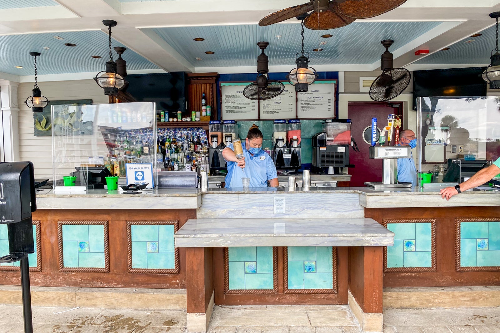
My 11-year-old gave the $6 Lava Smoothie (made of raspberry, coconut and pineapple flavors) high marks and my $14 Frosé was excellent.
Whether your group is made up of adults, some teens, tweens or toddlers, this pool area is truly excellent, especially if you build in some time to enjoy it when most people are sleeping, eating or in the Disney parks.
Evening movies on the beach
Several nights per week at 8 p.m., a Disney movie is shown along the "beach" at the Yacht Club. This is free to enjoy and the week we were there the films showing were "Zootopia," "Sleeping Beauty," "A Bug's Life" and "Disneynature: Earth."
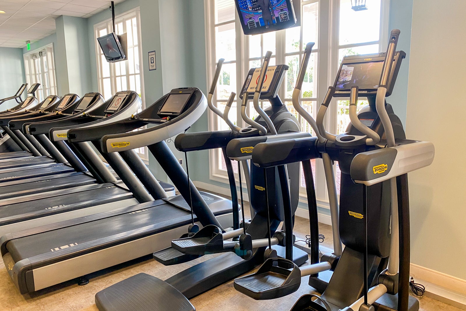
I'll never fully understand who needs a treadmill at Disney when it's normal to walk 10 miles a day in the park, but Yacht Club has those and more in its gym that overlooks Stormalong Bay.
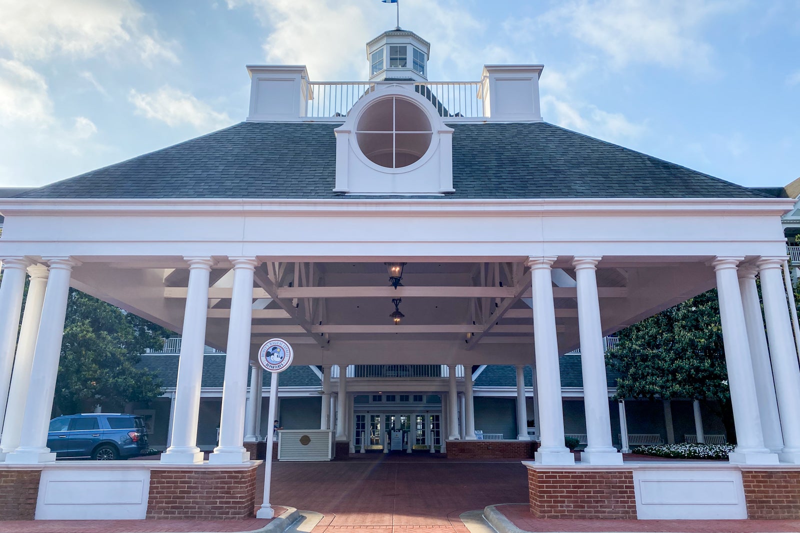
Magical Express Bus
Until the end of 2021, if you want to take the included Magical Express Bus transportation to and from the Orlando airport, that's available to those who stay at this and any other full-fledged Disney resort hotel. If you decide to self-park at Yacht Club, it's going to cost you $25 per night. The upside is that the fee also gives you access to parking at the Disney theme parks at no additional charge.
The Magical Express Bus stop is right in front of the hotel entrance, and the bus stop to go to the various Disney theme parks is just to the side of the hotel entrance.
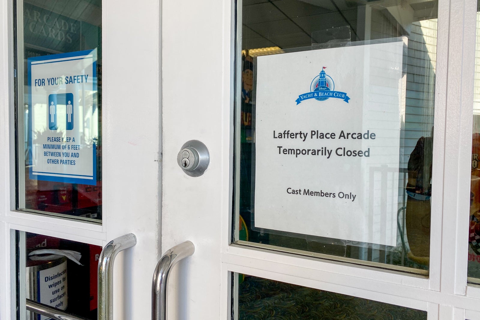
Still-closed amenities
If you remember when I mentioned there are still some small bumps at Yacht Club, here's where they begin.
Those looking for the ultimate, once-in-a-lifetime Yacht Club experience may want to hold off a tiny bit longer if you want to experience all the amenities. The Club Lounge remains closed, as does one of the main sit-down restaurants.
On top of that, the onsite Ship Shape Salon is still closed, along with the Lafferty Place Arcade.
Normally, you can rent boats or even sign your kids up for a pirate-themed adventure that leaves from the dock outside of the Yacht Club, but all of that is also still on pause.
We had plenty to do for a few days without any of those amenities, but just keep in mind that some things remain shuttered for now.
Related: Changes to expect at Disney World in 2021
Ale & Compass Restaurant
Just off the lobby of Yacht Club is a dark, subdued restaurant called Ale & Compass. While you do need reservations to eat breakfast or dinner here, it's one of the easier reservations to get at Disney World.
Described as "Yankee comfort food," this menu has options such as lobster-and-corn chowder; a fantastic salad called the Ale & Compass salad with additions such as pumpkin seeds and beets; steak; pasta; and a burger with bacon and Vermont cheddar served with thick fries.
Getting good photos in the dark restaurant was next to impossible, but we enjoyed our salad and burger.
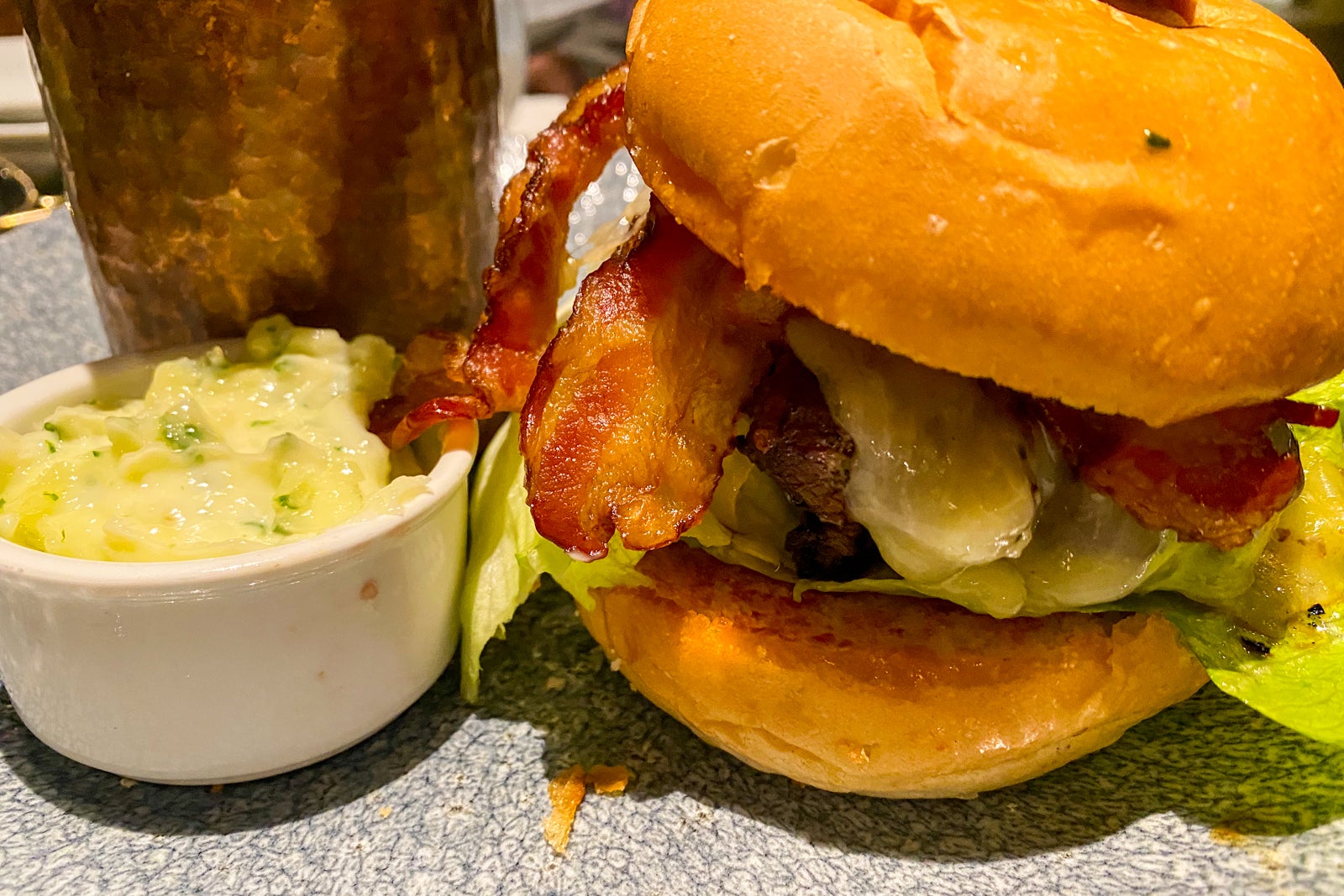
And while we didn't eat breakfast here, I've heard good things about the dark chocolate waffles.
Our service here was quite friendly but incredibly slow. The wait for our reservation was pretty extensive, followed by another wait for a server to arrive at our table to start the meal-ordering process. This is likely at least in part due to the restaurant having a brisk business of to-go orders that you can make from the Disney app, along with the other sit-down restaurant at the hotel remaining closed.
Related: These are the best restaurants at Disney World
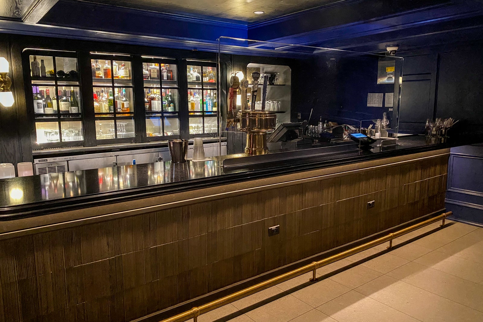
Ale & Compass Lounge
Another alternative to the restaurant is the adjacent Ale & Compass Lounge, which also has a sleek, updated, but pretty dark look once day turns to night.
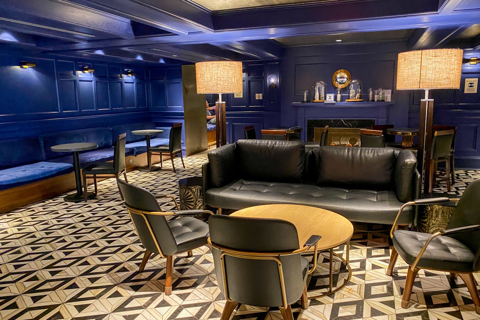
In the back of the lounge is a bar, with the front portion offering a variety of seating options and a reduced menu that still includes the burger and chowder.
The Market at Ale & Compass
In the gift shop area of the hotel is the Market at Ale & Compass, where you can order grab-and-go options in the Disney app.
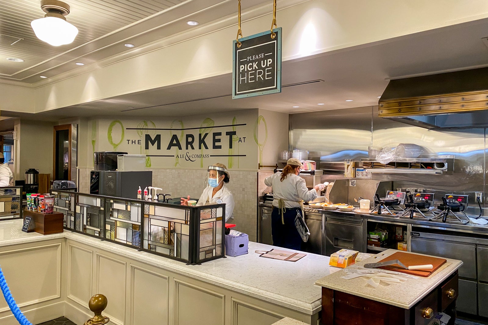
We tried the $12 breakfast bowl that had a little bit of everything on it and was actually almost enough food for myself and two kids for a quick pre-park breakfast.

The $7 ham and cheese breakfast sandwich on a pretzel roll also looked really solid.
In the afternoon and evening, you'll find a variety of sandwiches, a hot dog and a panini on the menu.
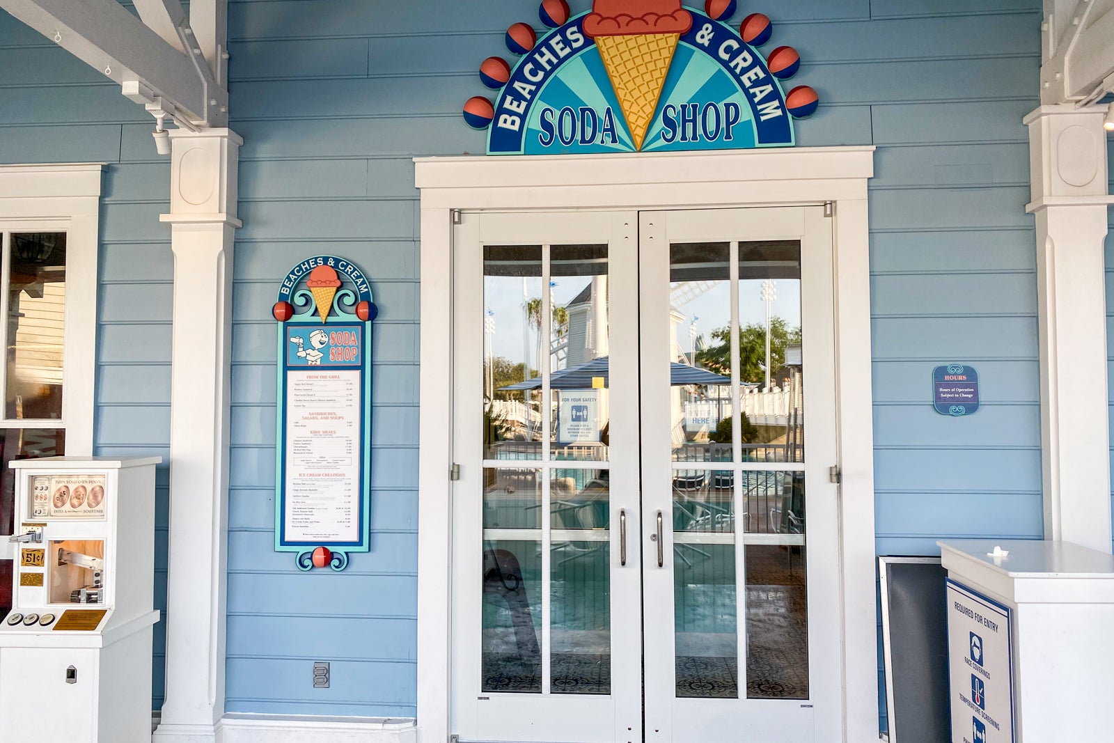
Beaches and Cream Soda Shop
If you're going to splurge cash on staying at the Yacht Club, I highly recommend also splurging some calories at Beaches and Cream. You're going to need to make a reservation here well in advance (dining reservations are accepted 60 days before your trip) or get very lucky.
We planned our trip pretty close-in and were never able to snag advance reservations, but got lucky with timing that they had an outdoor table available for us to order the most exciting item on the menu ... the Kitchen Sink.
This $35 sink of ice cream is made of eight scoops (vanilla, chocolate, strawberry, cookies and cream and mint) along with every single topping in the house. Oh, and there's also an entire can of whipped cream on top.
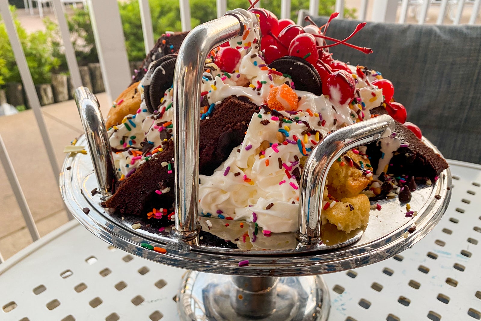
It's epic, huge, ridiculous and a lot of fun.
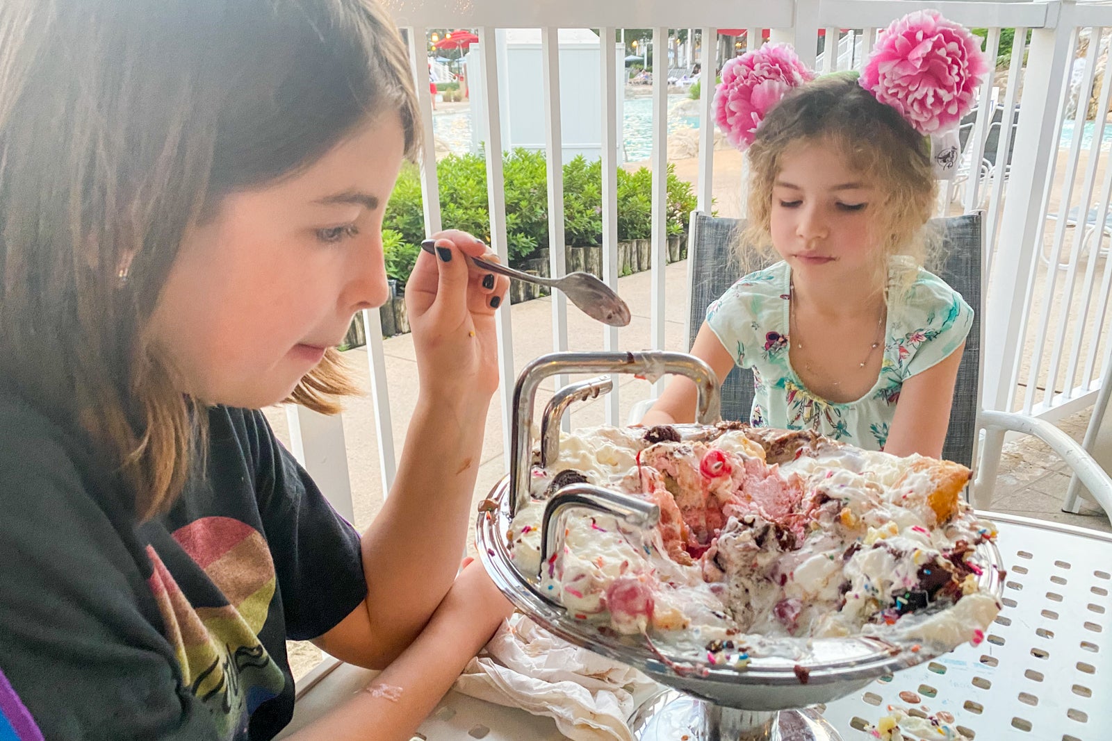
The three of us barely put a dent in it but certainly had fun trying.
There are more regular-sized ice cream options on the menu, too, but if you're doing a once-in-a-lifetime trip, try this once-in-a-lifetime dessert.
Should you want more than just sugar for your meal, this is also where you'll find burgers, sandwiches, chili and other 1950s classic-style treats.
Yachtsman Steakhouse
This second sit-down restaurant has not yet reopened, but when it does, this is where you can go for those post-convention expensed sales dinners ... or a very nice meal out for two. The menu features a $135 seafood tower, prime porterhouse, lobster, filet mignon, elk, lobster and other similar entrees that start around $50.
Overall impressions
I'm a total and complete sucker for a well-themed, well-located Disney World resort. Resorts such as this one, along with Disney's Polynesian Village Resort, Disney's Wilderness Lodge, Disney's Animal Kingdom Lodge and others, have me hook, line and wallet.
For me, the resort hotel isn't just a place to sleep at night, it's also a destination much like the theme parks themselves. I enjoy the scent in the lobby, the storyline of the property, the Disney touches throughout and the convenience of being fully immersed in Disney magic.
While my kids vetoed the idea, I'd have been totally happy having Disney's Yacht Club Resort serve as our actual final destination for the weekend with no park time at all. However, since it is such an easy walk to Epcot, adding that park on was actually a whole lot of fun, too.
If what you want is just a decent bed close to the parks, don't stay here. You're probably overpaying to stay at Yacht Club if you don't truly value the Stormalong Bay pool area. You can stay at the next-door Disney Swan and Dolphin for a fraction of the cash if you're just after location.
And right now, with some amenities still closed, I don't recommend staying here if you are going to be upset when things aren't 100% full service and perfect. The prices are as high as ever to match demand, so don't expect a reduced price to match the reduced amenities.
But if you can overlook a few things and what you want is a fun, slightly grown-up hotel theme, a great location, access to the best resort pool at Disney World and easy access to multiple restaurants, Disney's Yacht Club Resort is now officially one of my favorite Disney hotels — and one that I can't wait to return to in the coming years.
Disney’s Yacht Club Resort Review (Is it worth it?)

Disney’s Yacht Club Resort is one of the most beautiful and convenient hotels in all of Walt Disney World. With its classy design, enormous pool, and prime location, it’s easy to see why the Yacht Club at Disney World is such a highly sought after place to stay.
My family and I have visited numerous hotels on Disney property, but the Yacht Club always keeps us coming back for more. We love the close proximity to Disney’s Boardwalk, Epcot, and Hollywood Studios.
The multiple transportation options are a huge plus, especially for those who don’t like to solely rely on Disney buses. And of course we have to mention the Yacht Club’s pool, Stormalong Bay. This elaborate resort swimming area is arguably the best pool at the Walt Disney World Resort!
If you’re still not quite sold on the Yacht Club at Disney World or if you would like more information, continue reading below. In this post, we will cover everything you need to know about this deluxe Disney resort , including the activities, restaurants, and rooms available at Disney’s Yacht Club Resort.
(This post may contain affiliate links. If you make a purchase through one of these links, I may receive a small compensation at no extra cost to you. Please see my disclosure policy at the bottom of this page for more details.)
Yacht Club Restaurants
Disney’s Yacht Club Resort is full of all different types of restaurants. Since this hotel shares dining options with its sister resorts, you’ll find even more places to eat within a short walk of your room.

These are the Yacht Club restaurants you will find just a short stroll away:
- Ale and Compass – sit-down restaurant in the Yacht Club that serves breakfast, lunch, and dinner (also available to-go)
- The Market at Ale and Compass – quick service restaurant at Yacht Club with to-go items and menu options for breakfast, lunch, and dinner
- Yachtsman Steakhouse – fine dining restaurant at the Yacht Club that is open for dinner
- Crew’s Cup Lounge – bar at the Yacht Club that features a small dinner menu and full bar
- Cape May Cafe – offers a character meal breakfast buffet and sit-down dinner with no characters
- Beach Club Marketplace – features to-go items and menu options for breakfast, lunch, and dinner
- Beaches and Cream – available for lunch and dinner with reservations highly recommended
- Martha’s Vineyard – offers appetizers and full bar
- Hurricane Hanna’s Waterside Bar and Grill – pool restaurant with full bar and lunch/dinner options
Furthermore, the Yacht Club is located just a short walk away from Disney’s Boardwalk , where you’ll find additional restaurants and bars.
Disney’s Yacht Club Resort is home to the most popular pool on Disney property. It’s such a hit that you’ll find cast members handing out wristbands at the entrance so that only hotel guests can enter.

The main pool, Stormalong Bay, features a large sand bottom swimming area that’s super shallow and great for toddlers and little kids. There’s also a lazy river that’s a fan favorite in my household.
Guests can also enjoy other large swimming areas at Stormalong Bay, including an activities section where you’ll find games like pool volleyball. Stormalong Bay offers a large waterslide as well as a smaller slide that empties into a shallow pool.

In addition to Stormalong Bay, the Yacht Club in Disney World features a “quiet” pool that is seldom busy. This is a great spot to relax or swim laps.
Rooms
My family and I love the nautical decor and ambience of the Yacht Club guest rooms. Additionally, we appreciate that the rooms offer full balconies. In our post on Disney’s Beach Club vs Yacht Club , you’ll read about why these balconies are a major pro for Yacht Club compared to its sister resort.

Disney’s Yacht Club features standard rooms and club level rooms. If you book a room with Club Level benefits, you get access to the Regatta Club. Here, you’ll find food and beverages offered at certain times throughout the day.

Guest rooms at the Yacht Club come with views of the lake, pool, garden, or hotel rooftop/parking lot. These rooms typically feature 1 king bed or 2 queens. Some of them also offer a daybed. This means that if you book a room with 2 queens plus a daybed, you can sleep a family of five!
Prices at Yacht Club
Since Disney’s Yacht Club Resort is classified as a deluxe hotel at Disney World, you’ll notice that the prices are higher than at some of the other hotels. This is because the Yacht Club offers deluxe room space, extra amenities, and a prime location.
We will explain all the significance of all of these perks in more detail below, but it’s important to note that Disney’s Yacht Club truly offers a deluxe experience. The updated guest rooms feature plenty of space, including private balconies. Plus, the hotel is conveniently located within walking distance of other Disney hotels, restaurants, theme parks, and more.
If you would really like to experience the location, amenities, and entertainment at the Yacht Club without the hefty price tag, we suggest booking a room at the sister hotel through David’s Vacation Club Rentals. You will be blown away by the cost savings on David’s DVC rental site! We usually save hundreds of dollars per night by using this method to book a room at a deluxe resort.
Just use the cost calculator to see exactly how much a room costs at Yacht Club’s sister resort, Disney’s Beach Club Villas. These villas are located just a short walk away from the Yacht Club hotel, and they both share restaurants, pools, and activities. While you can reserve one of the villas on the official Disney website, we prefer to book through David’s DVC rental website . We have used this reputable company for years to rent timeshare points at Disney villas.
Things to Do at Disney’s Yacht Club
Disney’s Yacht Club Resort sits on the same property as two sister resorts: Disney’s Beach Club Resort and Disney’s Beach Club Villas. These three hotels share restaurants, activities, amenities, and entertainment options with each other.

One of my family’s favorite things about the Yacht Club is that you don’t need to leave the property to have fun. So, if you’re looking for activities at Disney outside of the theme parks, the Yacht Club offers lots of great options. These are our favorite things to do at Disney’s Yacht Club Resort when enjoying a relaxing day at Disney:
See Epcot Fireworks
We recommend walking to the bridge that connects the Disney Boardwalk to the Yacht and Beach Club Resort to enjoy the nightly Epcot fireworks show. You can even grab some ice cream to enjoy during the presentation.
Take a Ride on the Skyliner
Since the Disney Skyliner sits just outside of Epcot’s International Gateway entrance, you can easily access it from the Yacht Club Resort. Just take the short (less than ten minutes) walk toward Epcot and hop on the Skyliner for free!
Book a fishing excursion on Crescent Lake for a truly unique experience while staying at Disney’s Yacht Club Resort.
Eat Ice Cream
Disney’s Yacht Club is home to one of our favorite WDW restaurants, Beaches and Cream . While reservations can be difficult to snag at this popular dining spot, you can access the walk-up window to order shakes and ice cream to-go.
Dine with Characters
Check out Cape May Cafe during breakfast/brunch when it becomes Minnie’s Beach Bash. Guests can meet Goofy, Minnie, and Donald while they dine at the breakfast buffet.
Float along the Lazy River
The Beach Club’s main pool, Stormalong Bay, offers many fun features. One of our favorite things to do at the pool is to grab (free) tubes to float along the lazy river.
Play Games in the Arcade
Lafferty Place Arcade offers lots of fun games for kids and adults to enjoy. This is a particularly great place to spend time at Disney World when it’s raining.
Ride the Friendship Boats
The Disney water taxi picks up visitors near the Yacht Club. You can ride this free boat to the Disney Boardwalk, Swan and Dolphin Resorts, Epcot entrance, and Hollywood Studios entrance.
Build Sandcastles
Did you know that Stormalong Bay features a shallow, sand bottom pool and beach area? Kids love digging in the sand and splashing around in this section of the pool.
Make S’mores
Visit the nightly campfire to roast marshmallows during your visit. You can even purchase S’mores Kits for a few dollars.
Rent a Boat
Spend time on Crescent Lake on your own private pontoon boat. Guests can rent boats from the marina near the Yacht Club.
Disney’s Yacht Club offers a large fitness center for guests to use during their stay. Ship Shape Health Club is even open 24 hours a day, so you can squeeze in a workout at any time.
Stroll along the Disney Boardwalk
The Disney Boardwalk is full of amazing activities and entertainment options and is just a short walk away from the Yacht Club.
Play Volleyball
As you walk along the boardwalk in front of the Beach Club, you’ll notice a sand volleyball court. This is a great spot to pick up a game with friends or family. You can also often join a game of volleyball at Stormalong Bay Pool.
Enjoy an Evening Movie
Each evening, Disney Yacht Club guests can watch a movie under the stars. These family friendly movies are a great way to unwind after a long day.
Play Mini Golf
Stroll over to Fantasia Gardens and Miniature Golf Course where you’ll find two 18-hole courses. This fun spot is located near the Dolphin and Swan Resorts.
Swim Some Laps
If you’re looking for a quieter poolside experience to swim laps or relax, check out the leisure pool at Disney’s Yacht Club Resort. You’ll also have access to the quiet pools at Beach Club and Beach Club Villas.
If you’re not into running or jogging on vacation, you can spend time strolling along the jogging paths at the Yacht Club. You’ll find lots of great spots to take pictures and may even catch some surprises along the way.
Join a Kid Friendly Party at the Pool
Each afternoon, Stormalong Bay hosts fun poolside activities like hula hoop competitions and limbo.
Play Tennis
Guests can find tennis courts near the Yacht Club’s quiet pool.
Zoom Down Waterslides
Stormalong Bay features two separate water slides for guests to enjoy. The main waterslide stretches from the pirate ship and across the Beach Club boardwalk to the main pool.
You’ll also find a smaller slide that’s perfect for toddlers and small kids at the entrance to the main water slide.
Book a Fireworks Cruise
Take in the sights and sounds of the Epcot fireworks show from your pontoon boat on Crescent Lake.
Transportation
As mentioned above, Disney’s Yacht Club Resort sits in a prime location in the center of all the magic at WDW. If you’re planning to visit one of the theme parks, you’ll be happy to know that several of them are just a super short walk or ride away.

These are our preferred ways to get from Disney’s Yacht Club to other places in Walt Disney World:
- To Magic Kingdom – You can access the Disney buses in front of the hotel. The ride to Magic Kingdom should take 15-20 minutes.
- To Epcot – Exit the back of Yacht Club (toward Crescent Lake) and turn left. Epcot sits just under a ten minute walk away!
- To Hollywood Studios – You have several options for getting to Hollywood Studios. We find the quickest option *usually* is walking. Hollywood Studios sits just a 15 minute walk away from the Yacht Club. You can also ride a Friendship Boat to Hollywood Studios. However, by the time you wait on the boat to make stops, this method can take longer than walking. You could also walk toward Epcot to catch the Disney Skyliner. With this method, you should be able to reach Hollywood Studios in around 25 minutes.
- To Animal Kingdom – You can hop on one of the Disney buses to get to Disney’s Animal Kingdom Theme Park. This is roughly a ten-minute ride.
- To Disney’s Boardwalk – You can make the five-minute walk around Crescent Lake to easily reach the Disney Boardwalk. Guests can also take the Friendship Boat from the Yacht Club lighthouse and ride across the lake to the Boardwalk.
- To Disney Springs – You can take a bus to Disney Springs, which typically takes 15-20 minutes.
Is Disney’s Yacht Club Worth It?
Since Disney’s Yacht Club may be my personal favorite resort in all of WDW , I would definitely say it’s worth the cost! I love the classy guest rooms and bathrooms with their nautical decor.
The lobby seems to be quieter and calmer than that at other resorts, and the cast members are super friendly and helpful. My family and I enjoy the food at all the restaurants on site, and we appreciate the ability to easily walk from the Yacht Club to the Beach Club’s dining options.

The close proximity to Epcot makes the Yacht Club an ideal place to stay since there’s no rush to get to the park in the morning or back “home” at the end of a long day. Plus, you enter and exit through the International Gateway entrance to Epcot (near World Showcase), so the lines to enter are basically nonexistent.
Additionally, Disney’s Hollywood Studios is just a short walk, boat ride, or Skyliner ride away. And if you feel like venturing out, you can take the scenic stroll around Crescent Lake to the Disney Boardwalk.

Overall, we highly recommend the beautiful Yacht Club Resort! For additional information on Disney resorts, join the conversation on our Facebook page: Mom’s Guide to Disney Resorts ! Do you have a review of Disney’s Yacht Club Resort? Comment below to share your thoughts with us!
Shari is an experienced planner and organizer for Disney vacations, cruising, and U.S. travel. Her family vacation information, reviews, and tips provide insight for moms and dads everywhere. You can read more about her story, including her journey through breast cancer, in the about me page.
Similar Posts

Full List of Disney World Characters (Free Printable)

14 FUN Things to Do at the Polynesian Resort

Free Printable Disney World Packing List

Honest Review of Disney’s Wilderness Lodge at WDW

Unbelievably Fun Things to Do at Disney’s Boardwalk

Disney’s Beach Club Villas Review (with Tips)
Leave a reply cancel reply.
Your email address will not be published. Required fields are marked *
Save my name, email, and website in this browser for the next time I comment.
Disney’s Yacht Club Resort Review

Yacht Club Resort is a luxury hotel at Walt Disney World within walking and boat distance of Epcot and Hollywood Studios. This Deluxe Resort review features reimagined room photos, pool info, restaurant details, transportation benefits, other amenities, and pros & cons of these accommodations. ( Updated August 21, 2020 .)
During Walt Disney World’s phased reopening, Yacht Club Resort will be the first Crescent Lake area hotel to reopen. In fact, it’s nearby counterparts–Beach Club and BoardWalk Inn–don’t even have reopening dates set and may not reopen until sometime in 2021. (However, the Disney Vacation Club wings of each are already operating.)
After being one of the host resorts for the NBA’s bubble site, Disney’s Yacht Club Resort will reopen on August 24, 2020. When it does, some restaurants (including two favorites, Yachtsman Steakhouse and Crew’s Cup Lounge) will not reopen right away. Fortunately, most of the hotel will be operational, including Ale & Compass Restaurant and the Stormalong Bay pool complex. For a look at what’ll be different, see our Photos & Review of Walt Disney World Hotel Health Safety Modifications .
Disney’s Yacht Club Resort is themed to a New England yachting club. It’s an elegant and refined hotel contrasting with its more airy and lighthearted sister resort, Disney’s Beach Club Resort. The relationship between Yacht and Beach Club Resorts is an interesting one. They share facilities and are located next to one another, and are basically one giant resort complex.
However, despite their numerous similarities and shared features, Yacht & Beach Club are technically separate hotels. On the outside, the main noticeable differences for most guests will simply be color choices: Beach Club is light blue and Yacht Club is grey. It’s also abundantly clear when stepping into each lobby.

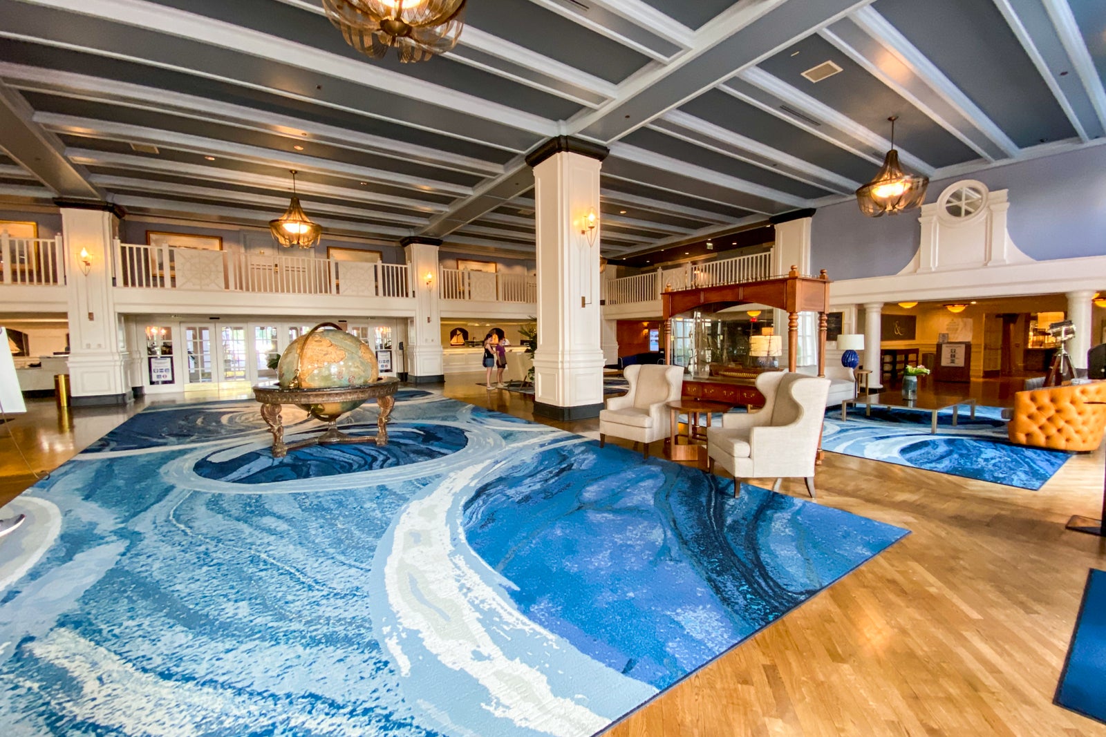
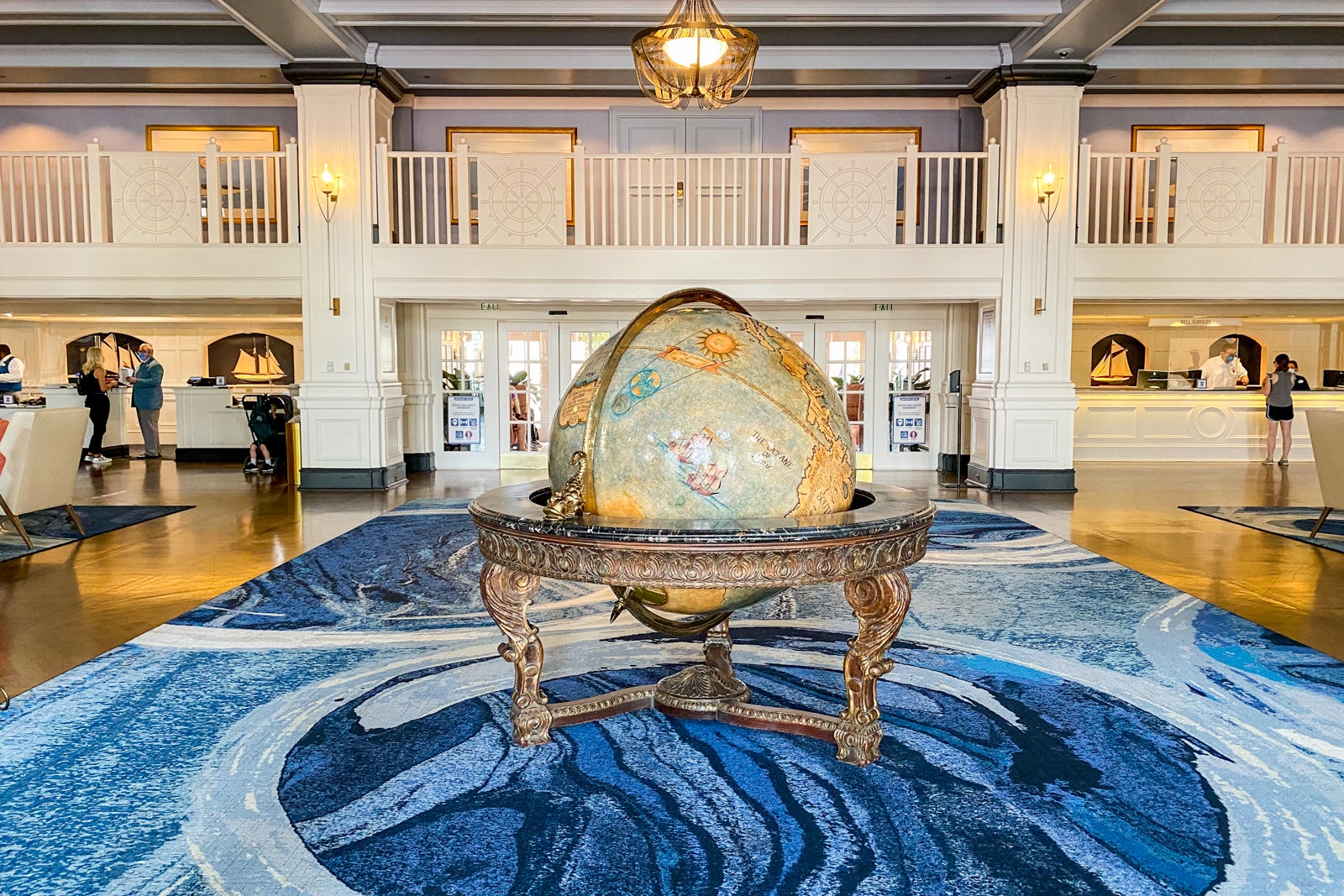
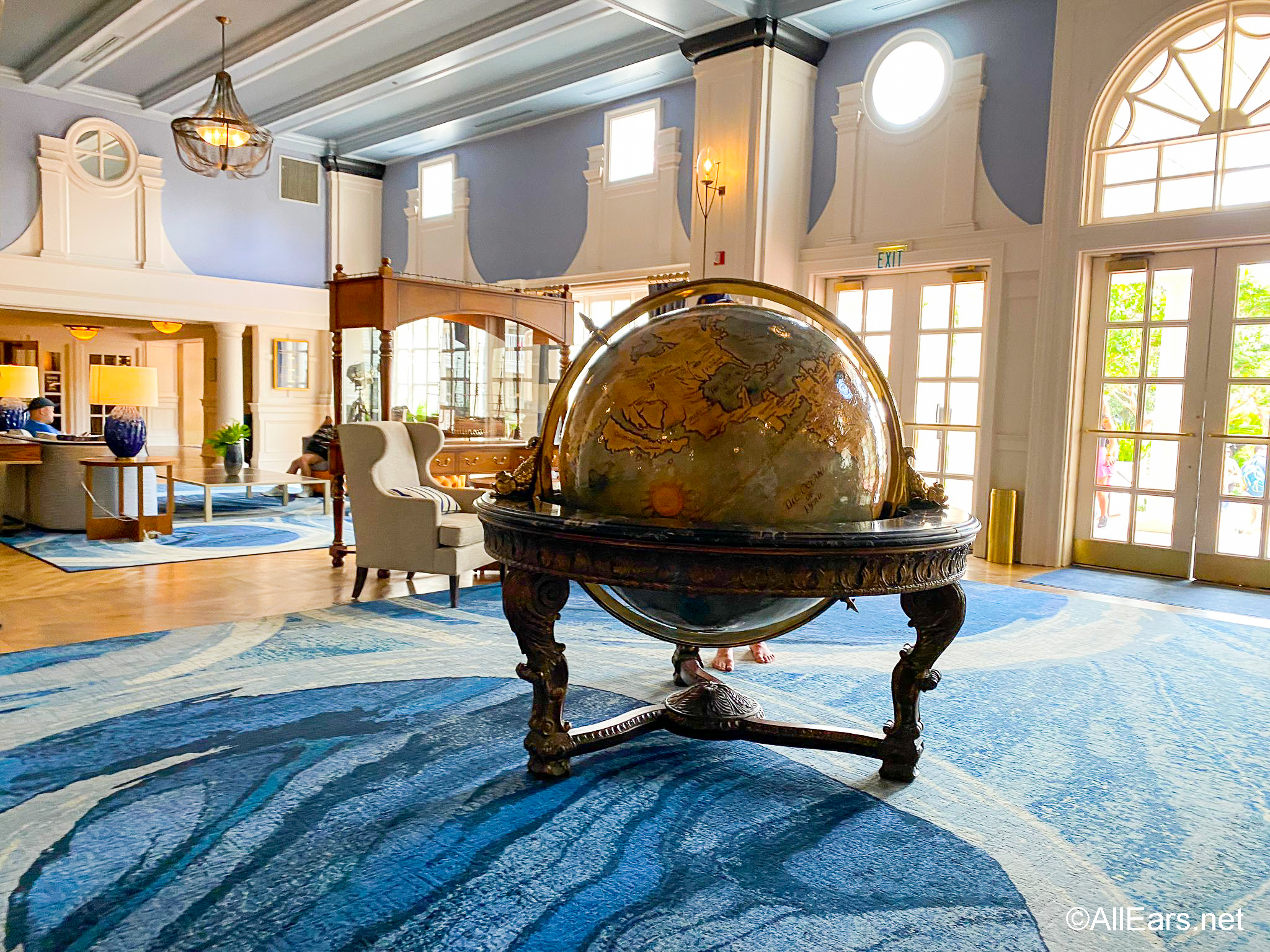
Yacht Club feels stately. With deep, masculine woods, dark colors, leather furniture, and an antique-looking globe, it reminds you of someplace that you’d imagine senators and titans of industry might have puffed on cigars and made power plays in the early 1900s.
By contrast, Beach Club is geared towards party-people who shout “I’M ON A BOAT!” from the bow of a ship . Okay, maybe not to those extremes, but the idea is that Yacht Club feels a bit more stuffy and refined in terms of theming, whereas Beach Club feels more relaxed and lighthearted.

Most people informally lump them together as one resort: Disney’s Yacht & Beach Club and overlook the thematic differences. We think this is a mistake. As we discuss in our Yacht Club v. Beach Club comparison, the differences in atmosphere are fairly pronounced, and this is likely driven in part by Yacht Club being one of Walt Disney World’s main convention hotels.
Let’s check out what the guest rooms offer…

These new rooms have been really divisive with Walt Disney World fans. Unpopular opinion, but we are big fans of the new look. Many fans have complained that they look drab and boring, but these are pretty consistent with the common areas of Yacht Club and there are a ton of subtle details and thematic touches.
We can understand why some people don’t like the new rooms given the colors now versus the patriotic color explosion of the old rooms (the old style was more cheery and lighthearted, but also off kilter with the resort’s otherwise stately appearance). The new Yacht Club rooms use of navy blue and beige contrasted against white, is really sharp in the context.

Beyond that, there’s an extensive use of dark woods, which really give the room an air of sophistication. It reminded me of the interior of a Brooks Brothers, oddly enough.
There’s also a variety of textures, the extent of which might be tough to ascertain from the photos. Our New Yacht Club Rooms Photo Tour shares more thoughts and images of the new rooms (including a different room style with a couch).

Much like BoardWalk Inn, Yacht Club is also great for the dashes of Disney presented in a restrained manner. The only Disney characters in the entire room appear in star constellations hidden on the curtain.
There are numerous other thematic flourishes reinforcing the nautical style, but many people want something overtly Disney in their hotel room. If that’s what you’re looking for, Yacht Club is not the resort for you.

The restrooms are divided, with double sinks outside of the shower and toilet area. Pretty standard–no complaints or praise here.
In terms of amenities, there is a nice benefit in their proximity of the Crescent Lake resorts to one another: better and more amenities as a result of sharing.

Between the Yacht Club and Beach Club, there are some seriously excellent dining options, including Beaches & Cream , Cape May Cafe , and Yachtsman Steakhouse , putting them, collectively, right up there with the best of the Deluxes in terms of quality restaurants.
We’ve also slowly become big fans of Ale & Compass Restaurant, which is a newer addition to Yacht Club. This is home to the Best Value Breakfast at Walt Disney World , and we highly recommend it.

Add to that the nearby Swan & Dolphin Resorts and Disney’s Boardwalk Inn , none of which technically share amenities but are so close that they might as well, and you have more high-quality restaurants within walking distance when staying at any of these resorts than at any other Walt Disney World hotel.
If dining is going to be a highlight of a trip, staying at one of the Crescent Lake resorts is the best option as there are numerous excellent dining options all within walking distance. This is especially true during Epcot’s International Food & Wine Festival, when you can graze and drink in World Showcase and then stumble back to your hotel!

Disney’s Yacht Club Resort has a ton of amenities, but it’s biggest selling point is Stormalong Bay. This is the crème de la crème of Walt Disney World pools. For those unfamiliar with Stormalong Bay, it is a sprawling 3 acre pool complex with sand at the bottom. That’s right, it’s a hotel pool with sand at the bottom!
Not only that, but it also has a lazy river, an excellent ‘shipwrecked’ water slide, tons of places for lounging, and an excellent poolside bar. While many Walt Disney World resort hotels now no longer allow “pool hopping,” this was the first that introduced the concept, and the pool that most vigorously enforces the no-hopping rule. The excellence of this pool really cannot be understated. It’s basically a mini water park. (For everything you need to know about Stormalong Bay and its policies, see our Guide to Pools at Walt Disney World: Rules, Info & FAQ .)

The close proximity to both Epcot and Disney’s Hollywood Studios (we consider both walking distance, but most guests opt to take a boat to Disney’s Hollywood Studios instead of the 15 minute walking path–even if the path is usually faster) is another huge benefit. Boat service is also available to both parks, and it’s a certifiable fact that boat transportation at Walt Disney World is awesome.
Additionally, there’s now a Skyliner station at Epcot’s International Gateway, which means guests staying at Yacht Club can walk there and take the gondolas to Hollywood Studios, Caribbean Beach, Pop Century, Art of Animation, and Riviera Resorts. That can be useful in opening up other dining options. (Plus, the Skyliner is just plain fun.)

On the other hand, bus transportation is decidedly un-fun. Getting to Magic Kingdom and Animal Kingdom via bus can be a hassle. There’s always some sort of shared bus service operating, but exactly how many buses share the service depends upon the season.
When you consider the prices guests are paying to stay at a Walt Disney World resort hotel with “Deluxe” accommodations, it’s ridiculous that the buses make stops at multiple resorts. It’s frustrating that Pop Century, a budget hotel, has dedicated and efficient bus service but it can take an hour to get to Magic Kingdom via buses from the pricey Epcot-area resorts. (Although makes us happy when we pay the comparative bargain price to stay at Pop Century!)

Disney’s Yacht Club Resort offers other amenities, including a health club, volleyball court, arcade, marina, business center, babysitting, tennis courts, and other recreational facilities, but none of these measure up to Stormalong Bay. This pool complex is the ultimate trump card that makes Disney’s Yacht Club and Beach Club Resorts stand out from the other Deluxes.
All of this comes at a cost, as rates at Disney’s Yacht Club Resort start at around $400 per night and go up from there depending upon the season and room category. This puts it among Walt Disney World’s most expensive hotels, but still not as expensive as the Magic Kingdom area hotels. While we love the Yacht Club, we would not stay here without a 30% off room-only Walt Disney World resort discount or the Free Disney Dining Plan promotion .

Overall, Disney’s Yacht Club Resort is a solid option for a Deluxe Resort stay at Walt Disney World. The pool is great, the restaurants are solid, and location is great for visiting Epcot and Disney’s Hollywood Studios. Yacht Club is especially appealing if you’re a New Englander from Nantucket who wears an ascot aboard your vessels.
Joking aside, Yacht Club’s theme is a bit more taste-specific and adult. Those considering Yacht Club are probably also considering Beach Club. For us, the overall ambiance and laid back vibe of Beach Club screams “vacation” in a way that Yacht Club just doesn’t, and this ambiance appeals to us. Still, both resorts are great options–two of our favorites at Walt Disney World–and whether you should choose Beach Club or Yacht Club if considering the two should really only be a question of whether you prefer the elegant nautical look or the relaxed beach look.
Not sure which Walt Disney World hotel is right for you? Let a professional help you for free. Click here to get a quote from a recommended, no-fee Authorized Disney Vacation Planner . They get their commission from Disney, so there is no charge to you for them to book your trip and help you plan!
Check out our Walt Disney World Hotel Reviews page , which offers quick-hit capsule reviews of the strengths and weaknesses of every Walt Disney World hotel, plus links to our reviews and photo pages for every hotel we have reviewed. Looking for comprehensive Walt Disney World vacation tips? Make sure to read our Walt Disney World Trip Planning Guide .
Your Thoughts
Do you agree with us that Disney’s Yacht Club Resort is one of the best Walt Disney World hotels? Do you think Stormalong Bay lives up to the hype? Any questions we can help you answer? Hearing feedback about your experiences is both interesting to us and helpful to other readers, so please share your thoughts below in the comments!

Written by Tom Bricker

They lost our car key. This place is a disaster if incompetence. They don’t care about anyone.

Completely disagree on Yacht Club being at all stuffy! We usually stay at Beach Club but booked Yacht Club with our three kids, 18, 16, 9, in April and FELL IN LOVE!! The staff was excellent, rooms simple & clean, lobby beautiful and airy, convenient shop-not a snobby, stuffy vibe to be felt. Last time we stayed at BC the room (Club level) was dated, felt small and had peeling paint on the wall! We alway stay in walking distance to Epcot because of the food and later hours. Yacht Club is our new favorite. The entire experience was like a dream. Also, we did the masks in 90 degree weather and were surprisingly unbothered. Every staff member we interacted with was wonderful. And we are Northern MI folk. I can assure you, none of us own yachts or ascots

^ wes’ comment about starving to death is 100% accurate. the resort has over complicated everything “because of covid.” you can’t just walk in anywhere, the staff is rude and condescending. we are staying in a villa paying out the ass and they won’t even change our sheets? hello? how do the other hotels manage? don’t get me started on the self righteous mask police here. if you are outside alone not surrounded by anyone for WAY over 6 ft you MUST wear a mask, in the 90% humidity and 90 degree weather. but as soon as you step foot in the pool no masks required. covid knows when and when not to be contagious. also you can sit INSIDE surrounded by people without a mask. but not outside guys. such a joke. the staff here all give you different answers as well. would never stay here, would rather stay at a motel 6. we are speechless at how rudely everyone has treated us.
forgot to mention last night we called the front desk for water. we waited an hour and called to follow up on the water and were told they only have two bottles and we would have to come get them ourselves. for a 20k villa we expected much more, this is below what i would expect from a hole in the wall hotel.
on a positive note the best thing about this resort is the ferry transportation to and from the parks, the location and the actual room is great. that’s literally all i can come up with it. really bad customer service.

I have lost 10 pounds since we’ve been here. You will starve to death. I am considering flying home two days early. About 65% of the staff have been great, but the others act like they are miserable. This is the furthest thing from hospitality you could imagine. I have been to jail before and it wasn’t this bad. If you want to lose weight quick and want to feel like a second-class citizen, stay here.
Your email address will not be published. Required fields are marked *
Save my name, email, and website in this browser for the next time I comment.
Notify me of follow-up comments by email.
Notify me of new posts by email.
I stayed solo at Disney's Yacht Club resort for $750 a night, and its many perks made it worth every penny
- I recently stayed by myself at Disney's Yacht Club resort for $750 a night.
- My room had a great balcony and Yacht Club has an amazing pool and lazy river.
- It's my favorite resort on Disney World property because of its dining and proximity to parks.
I recently stayed at Disney's Yacht Club resort, a deluxe resort located in the Epcot area of Disney World.
The resort is themed to feel like an upscale New England-style hotel with nautical touches throughout the lobby and hotel rooms. When I visited, I paid $750 a night for my standard-view room with two queen-size beds and a balcony.
I chose to splurge on this resort because I was traveling by myself. I love being a short walk away from dining locations and bars when I'm traveling alone and this location and its pool area simply cannot be beat.
Here's what my stay was like and why Disney's Yacht Club resort remains my favorite hotel on the property.
The standard-view room I stayed in March was priced at $750 per night.
Rooms at the Yacht Club start at $484 per night for a standard view and can go well into the thousands for suites and club-level accommodations, depending on the time of the year.
My room had two queen-sized beds, a balcony, and a view of the front gate of the resort. The room was equipped with a pull-out couch, mini fridge, a safe, Keurig coffee machine, and ample storage space for clothes and luggage underneath the beds.
The room featured furniture in dark wood tones with brass accents.
I appreciated the conveniently placed reading lights built into the headboards and ample plugs for charging devices near the beds. My room also had a writing desk.
The bathroom featured a double vanity, a large shower stall, and products from cult-favorite Disney brand H20+.
H20+ products are often found in Disney resorts and many guests love them. On this trip, I got a shower cap, mouthwash, facial soap, body lotion, and vanity kit in my room.
Many Yacht Club rooms have sizable balcony areas.
One reason I prefer the Yacht Club over Disney's Beach Club is the size of the balcony that comes with most rooms.
Many Beach Club resort rooms feature small Juliet-style balconies, but the Yacht Club seems to have more rooms with large balcony areas. I love to spend as much time on the balcony as I can and this is always a deciding factor for me when I'm selecting what resort I book for a trip.
The Yacht Club has several standout locations for drinking and dining.
Located on the resort property, Yachtsman Steakhouse is a classic steak house with a loyal fan following. The menu has premium steaks that are cut in house and a wide selection of vintage wines.
Next to the steak house is Crew's Cup Lounge. The rowing-themed lounge serves beer, wine, and cocktails as well as a limited selection of food items from the kitchen at the Yachtsman, making it a perfect stop if you weren't able to score dinner reservations.
Just off of the Yacht Club lobby is Ale & Compass.
The gastro-pub-inspired restaurant offers both a buffet and an a la carte menu for breakfast. It also serves New England favorites, like Parker House rolls and fish and chips for lunch and dinner.
There's also Beaches & Cream Soda Shop, located between the Yacht Club and Beach Club.
The Beach Club resort is in the same building as The Yacht Club, so its dining options are also easy to access.
The two also share Beaches & Cream Soda Shop , Disney's spin on a retro soda fountain. It serves burgers, sandwiches, and ice-cream classics by the scoop or in a sundae or float.
The resort has a massive pool area, Stormalong Bay.
Stormalong Bay is often regarded as the best pool in the fleet of Disney resorts . Guests must prove they're staying on the property to access this pool area — most Disney resorts don't do this.
The 3-acre shipwreck-themed area features a sandy-bottom pool, a lazy river, several whirlpool spas, and one of the highest hotel waterslides in Disney World.
Guests looking for a more peaceful pool experience can go to the Admiral Pool, located in a more quiet area of the Yacht Club resort.
At the pool, you can rent a cabana or grab a bite to eat.
At the pool, guests can also rent a cabana with shaded canopies and plush loungers for an additional fee.
Adjacent to the area is Hurricane Hanna's Waterside Bar & Grill, where you can get cocktails and classic poolside favorites like cheeseburgers and fries.
The Yacht Club is a 10-minute walk from an Epcot entrance and a 15- to 20-minute walk from Hollywood Studios.
Yacht Club is conveniently located near multiple Disney parks and — in addition to walking — guests have multiple transportation options.
First off, both Epcot and Hollywood Studios are within walking distance of the resort.
The resort is also steps away from the Friendship Boats that ferry guests across Crescent Lake between Epcot, Hollywood Studios, and a few other Disney resorts.
It's also near the Skyliner, which is connected to other resorts and Hollywood Studios. Bus transportation is also available to Magic Kingdom, Animal Kingdom, Hollywood Studios, Disney Springs, Typhoon Lagoon, and Blizzard Beach .
The resort is also just across the lake from the Disney BoardWalk.
The BoardWalk features midway games, evening performers, and a number of restaurants and bars. You don't need a theme-park ticket to check it out, either.
Overall, Yacht Club is ideal for folks who want to spend most of their time at the resort or the nearby parks.
Yacht Club resort is great for guests planning to spend a lot of time at their hotel — or Epcot and/or Hollywood Studios. The resort's close proximity to those two parks makes it a great choice for travelers who enjoy taking a midday break.
With its many on-site dining options, Yacht Club is an excellent choice for folks who prioritize being able to get a great meal without traveling far. If you value a great pool while on vacation, it's also hard to beat either the Beach or Yacht club.
With all of that in mind, the Yacht Club is one of my absolute favorite resorts on Disney World property and absolutely worth the price point.
When you buy through our links, Insider may earn an affiliate commission. Learn more .
- Main content

Accommodations
Theme parks, disney cruise line – what you need to know, cruise line ships, recent walt disney world, recent disneyland, all reviews, recent reviews, allears style, newsletter home, recent disney and florida attractions news blog.
- NEW Airline Refund Rules Could Change the Way You Fly
- You Only Have 18 Minutes To Be One of the LUCKIEST People in Magic Kingdom Each Night
- A NEW Disney Series Just Premiered on YouTube!
- NEW Food Booth Details REVEALED Ahead of Disney’s 2024 Pixar Fest
- Okay, This Might Be the COOLEST Job You Can Have at Disney World!
- ( view all posts )
Ultimate Guide to the Best Rooms at Disney’s Yacht Club Resort

Staying at a Disney World deluxe resort usually comes with beautiful theming, nice rooms, and perks like Extended Evening Hours . One might argue, though, that one of the most beautiful deluxe resorts in Disney World is Disney’s Yacht Club .
This deluxe resort is a popular choice for guests wanting easy access to EPCOT or Hollywood Studios, which are both just a walk or boat ride away, or because of the epic pool, Stormalong Bay, which is almost like its own waterpark. It’s easy to decide why guests stay here, but, which rooms are the best ?
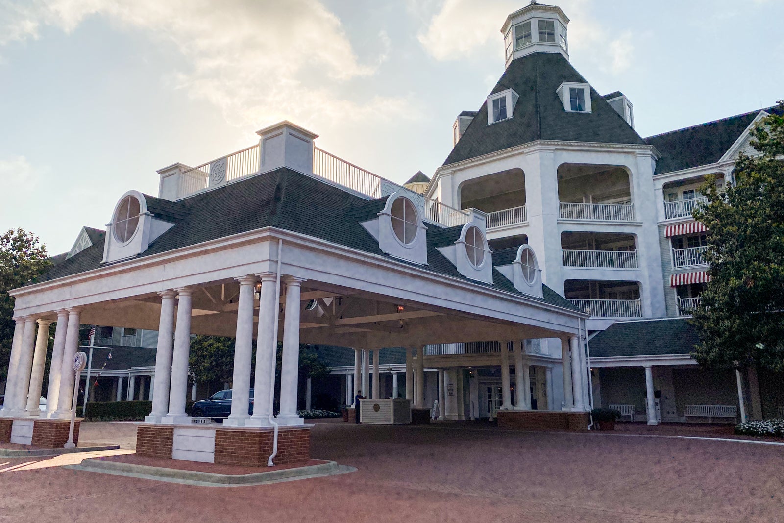
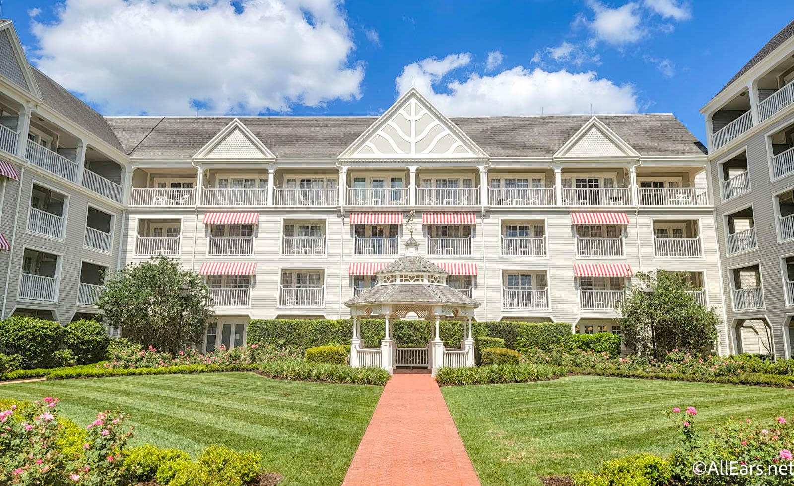
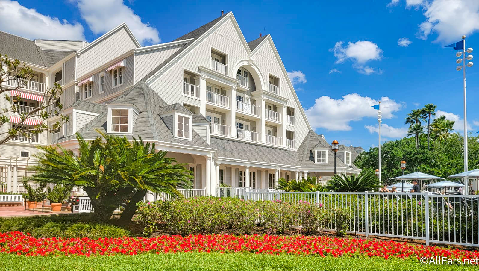
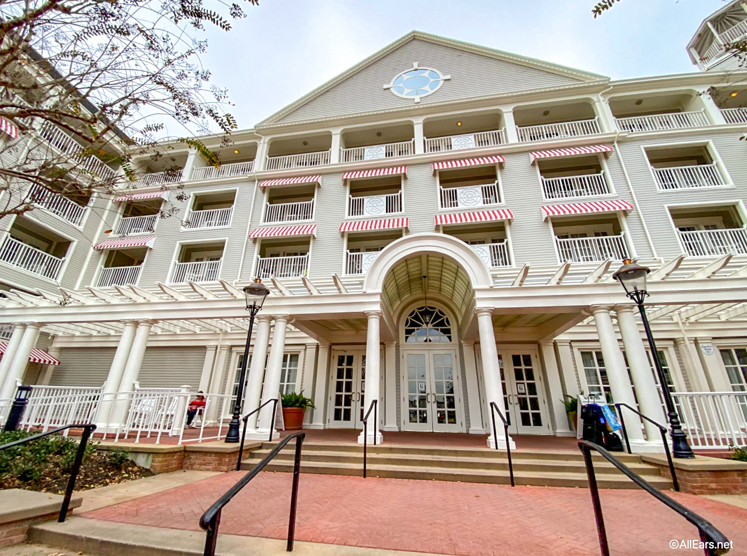
The Yacht Club is a five-story deluxe resort and is themed around the refinement of a New England yachting club. The resort has a soft gray exterior accented by striking red and white striped awnings and the interior is lined with warm woods, nautical instruments, and a giant globe as the lobby centerpiece. The resort faces Crescent Lake, is close neighbors with Beach Club Resort, and has the best resort pool on property. You’ve picked a beautiful resort to spend your Disney vacation, but let’s look at the best rooms!
The Yacht Club rooms are elegant and stately and might be a bit “executive” and bland when compared to some of its counterparts. Keeping with the nautical theme, you’ll find warm woods, navy blue and beige contrasted against crisp white. But one of the favorite elements in the room are the navy curtain which features fictional Disney constellations and a bit of whimsy to this otherwise rather corporate feeling room.
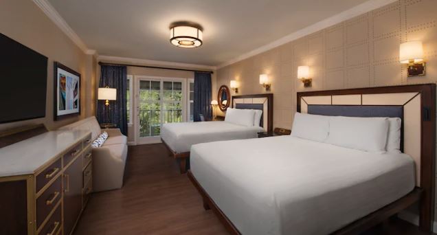
There are 635 guest rooms and 21 suites at the Yacht Club. The rooms are typically 381 square feet and feature two queen-size beds, a daybed, and a desk with chairs. There are some different categories to choose from: Standard View, Garden View, Water View, and Lagoon or Pool View .
For an extra cost, there are also 70 club level or concierge rooms on the fifth floor Regatta Club. Those these rooms are basically the same as standard rooms, they do offer access to additional amenities, including:
- An exclusive check-in area
- A concierge cast members to assist with personal vacation needs
- Nightly turndown service
- Access to a club lounge stocked with complimentary food and beverages
4th Floor Rooms
The top floor is typically reserved for the Club level rooms, but the next best thing without that concierge price tag is the fourth floor. These rooms provide better views (no matter what you’re direction you’re looking), but particularly if you have a Pool View where lower level rooms would just give you views of the back of pool lounge chairs.
Gazebo View
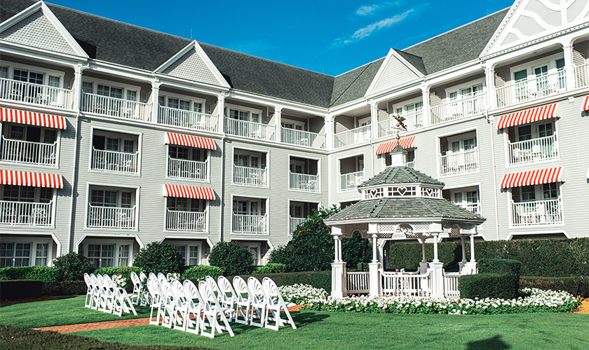
You won’t find “Gazebo View” listed in the options, but rooms ending –48, –50, –52, –54, and –63, as well as odd-numbered room –67 through –97 over look the gazebo which make for a serene view. And you even be in for a show if one of the Disney’s Fairytale Weddings occurs there during your stay (no invitation required!).
Corner Rooms
Rooms that fall on the corner of buildings sometimes come with a little extra elbow room or even an extra window. For that chance to snag not just one views, but two look at these options, rooms ending in: -001, -009, -114, -122, -027, -043, -065, -155, -163, -164, -201, -209, -210.
If you’re looking to be closer to EPCOT, Stormalong Bay, and the Beach Club, ask for rooms ending in -190 through -241. If you’re looking for rooms closer to the Swan and Dolphin and Hollywood Studios, ask for rooms ending in -001 to -054.
So if you’re looking to book a stay at Disney’s Yacht Club and want the best room available, keep these in mind! You can also always check out our reader reviews of Yacht Club here .
The Ultimate Guide to the Best Rooms at Disney’s Polynesian Village Resort
Join the allears.net newsletter to stay on top of all the breaking disney news you'll also get access to allears tips, reviews, trivia, and more click here to subscribe.
Have you ever stayed at Disney’s Yacht Club Resort? Let us know in the comments!
Trending Now

From time to time, rides and attractions are taken out of production temporarily for various...

We found your perfect Hollywood Studios tee.
There's a NEW roller coaster coming to Epic Universe in Universal Orlando, and we've got...

You may be taking a BIG risk to get on this Magic Kingdom attraction. Here's...
We're rounding up the best souvenirs in Magic Kingdom's Tomorrowland!
One Disney World park is about to celebrate a big milestone!

Your jaw will DROP when you see the NEW Disney popcorn buckets coming soon!

Disney teased a NEW theme park expansion and we have an update on a ride...

This job at Disney's Animal Kingdom is for the WILD at heart.
We use these seven cheats at Disney World's EPCOT all the time.

A NEW Disney show has premiered on YouTube but you can check the first episode...
Take a look at ALL of the merchandise at the 2023 EPCOT Flower and Garden...

I hope you’re hungry because we’re talking about 24 of the BEST Restaurants in Disney...
We have a big Smellephants on Parade update in Magic Kingdom!

This Disney Loungefly is a little late to the party...bur nevertheless you can snag it...
Let's take a look at everything that's been confirmed to return so far.

I go to Disney World alone A LOT, and these are the restaurants that never...
We've got some of the BEST Cast Member tips just for YOU!
A NEW rule has changed air travel in the United States forever -- get the...
Fill in the missing words to find out how well you know the Pirates of...
Leave a Reply Cancel reply
Your email address will not be published. Required fields are marked *
Follow us on Social!

Shop the Disney Store | AllEars® Merchandise | Shop Amazon | Press Room | Contact Us
Read more About us or Advertise with us . We respect your right to privacy. Please take a moment to review our privacy policy and terms of use .
Copyright ©1996-2024 AllEarsNet, LLC, All Rights Reserved. AllEars.Net, AllEars® Newsletter and any other properties owned by AllEarsNet, LLC are not affiliated with, authorized or endorsed by, or in any way officially connected with, The Walt Disney Company, Disney Enterprises, Inc., or any of their affiliates. All Disney artwork, copyrights, trademarks, service marks, and trade names are proprietary to Disney Enterprises, Inc. or, its subsidiary, affiliated and related companies. For official Disney information, visit http://www.disneyworld.com
- Skip to right header navigation
- Skip to main content
- Skip to primary sidebar
Plan Your Dream Trip To Disney!

The Ultimate Disney Yacht Club Review + Insider Tips
February 8, 2021 // by Kimberly Jones // 2 Comments
Disney’s Yacht Club opened back on November 5, 1990. Its sister location is the Beach Club located right next to it. The Yacht Club is a beautifully themed resort with nautical and beach themes. We are going to tell you everything you need to know about this wonderful resort in our Ultimate Disney Yacht Club Review + Insider Tips!
There are so many great aspects to this resort such as its location, pools, transportation options, and amenities. If you are thinking about staying at the Yacht Club, read on to find out if this resort is a good fit for you!

Where Is The Yacht Club At Disney Located?
One of the best reasons to stay at Disney’s Yacht Club is the fantastic location! This resort is within walking distance to Epcot and Hollywood Studios . There are also several different transportation options to all of the parks, Disney Springs , and the water parks .
The Yacht Club is directly next to the Beach Club, and they share the pool. Now you not only have access to all of the Yacht Club’s restaurants and amenities, but you also have access to the Beach Club’s!
The Yacht and Beach Club are right across the water from Disney’s Boardwalk Resort . It is a short walk away to enjoy everything the Boardwalk has to offer! There are some fun restaurants, bars, and shops to explore there.
The Yacht Club is also very close to the Swan and Dolphin Hotels. There is a pathway to take you right over to these hotels for some extra fun as well!
Not only are there other resorts within walking distance of the Yacht Club, but there are also resorts that are a quick Skyliner trip away! Taking the Skyliner from Epcot’s International Gateway, you can visit Disney’s Riviera Resort, Caribbean Beach Resort, Pop Century , and Art of Animation!
Disney’s Yacht Club is in a very prime location with quick access to two of the parks and multiple resorts!

Checking in to The Yacht Club At Disney
Checking into the Yacht Club is extremely easy, and it doesn’t even require you to visit the front desk! The day of your reservation, you can check in to the resort from the My Disney Experience app . The app will let you know when your room is ready and what your room number will be! If you have magic bands or even your phone , you can head straight to your room and unlock the door.
Of course, you can always go the old school route and check-in at the front desk. All the cast members at Disney’s Yacht Club are extremely friendly and accommodating! A great tip to keep in mind is you can always see if there are any upgrades available for your room. We were able to get a free upgrade from a standard view to a water view!
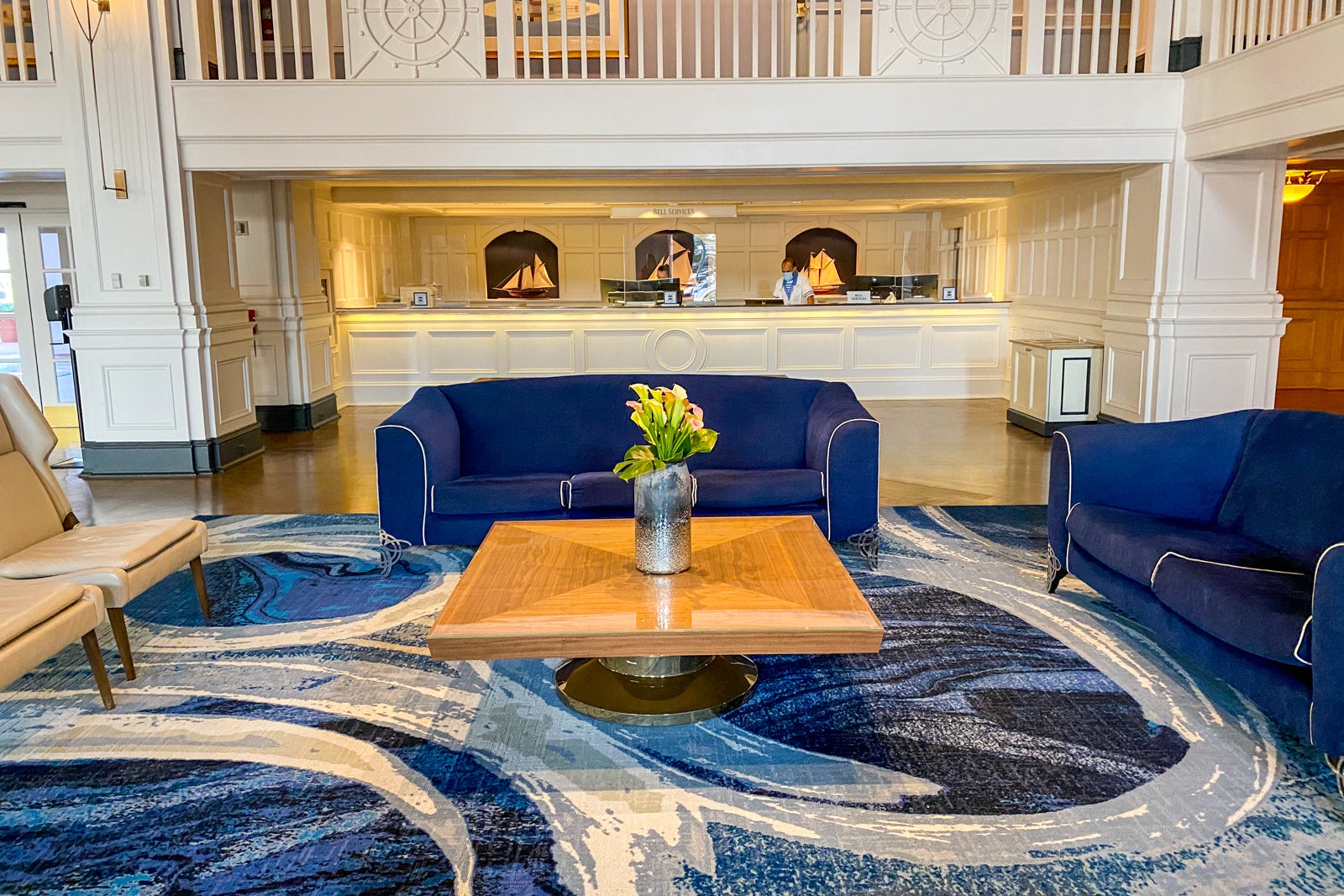
The lobby is also absolutely amazing here. It has a very adventurous and nautical theme to it. You can find everything you need right in this area, such as the restaurant, lounge, bell services, and the front desk.
Right outside the backside of the lobby, there is a boardwalk that will lead you to the boat transportation to Epcot and Hollywood Studios.

Transportation Options From The Yacht Club
We love all of the transportation options the Yacht Club has to offer, and we’re sure you will too! As mentioned before, there are walking paths to Epcot and Hollywood Studios. The Epcot walking path is very short and will get you to the International Gateway in about 5 – 10 minutes. The entrance at International Gateway is on the back side of Epcot by World Showcase .
The walking path to Hollywood Studios is a little bit longer than the Epcot one. This one can take 20 minutes or more. However, there is boat transportation to Hollywood Studios if you don’t want to walk! You can find boat transportation right behind the lobby that will take you to Epcot or Hollywood Studios.
If you don’t want to walk or take the boat to Hollywood Studios, you can always take the Skyliner! There is a Skyliner location right outside International Gateway that will take you first to Disney’s Riviera Resort, and then to the Skyliner central hub at Caribbean Beach Resort. From here you will get off the Skyliner and get in line for a different Skyliner track to take you to Hollywood Studios.
So there are so many options to get to Epcot and Hollywood Studios, but what about the other parks? Disney has bus transportation from the Yacht Club to Magic Kingdom, Animal Kingdom, Disney Spring, and the water parks.
If you plan on spending a lot of time at either Epcot or Hollywood Studios, the Yacht Club is one of the best resorts to stay at.

Disney Yacht Club Room Review
There are several different room options at the Yacht Club. There is Standard View, Water View, Garden or Woods View, and 2 Bedroom Suites. All of the view rooms also have club level options.
I was able to stay in a Water View room. The room was absolutely delightful! It had a nautical theme to match the rest of the resort, and it was quite spacious. The room had two queen beds and a pull out couch, so it was able to sleep up to 5 guests. We only had 4 guests in our room, but I could imagine the pull out bed might make the room feel a little more cramped.
The room had large closets with space to hang clothes, and a big sink and bathroom area with two sinks. The shower had a sliding glass door, which I prefer over a curtain.
I really liked that this room had wood flooring compared to carpet. It added to the nautical theme very well. The room also had a balcony that looked over the back entrance of the lobby and the water. Overall, the room was very nice, and I thoroughly enjoyed its set up!
Yacht Club rooms average in price anywhere between $400 to over $3000 per night depending on what room you stay in and what time of the year you visit.

Dining Options At The Yacht Club
There are some really great and delicious dining options at the Yacht Club. This resort has two restaurants, two lounges, a quick service restaurant, a restaurant located in between the Yacht and Beach Club, and a pool bar.
The two restaurants at the Yacht Club are Ale & Compass and Yachtsman Steakhouse. Yachtsman Steakhouse is currently temporarily unavailable, but Ale & Compass is open for breakfast and dinner. This restaurant follows the nautical theme with a relaxing atmosphere and some delicious coastal eats.
The Ale & Compass Lounge is located adjacent to the restaurant. Here, you can order off the lounge menu and even the restaurant menu. This lounge can fill up quickly at night though, so make sure to grab a seat early if you want to eat or drink here.
The other lounge, Crew’s Cup Lounge, is right next to Yachtsman Steakhouse and is also temporarily unavailable. We hope that the lounge and restaurant will open soon!
The quick service location shares a spot with the Yacht Club’s gift shop. When you enter the Market at Ale & Compass, on the right is the gift shop and on the left is the quick service restaurant. They serve coffee, sandwiches, pastries, and more. This is a great place to stop for a quick bite to eat to or from the parks!
Beaches and Cream Soda Shop is the hidden gem of the Yacht and Beach Club Resorts! This restaurant is located in between the two resorts and serves some wonderful food! They are open for lunch and dinner and they serve sandwiches and burgers. My favorite is their Grilled Cheese sandwich, its delicious!
However, save room for the best part of this restaurant. The ice cream! They have shakes, floats, and sundaes! You can’t go wrong with whatever you choose. If you’re feeling really brave though, try the Kitchen Sink sundae. This sundae is meant for 4 or more people, and includes every topping and a whole can of whipped cream! I have attempted it twice, and I still haven’t been able to finish it. Maybe you can!
Hurricane Hanna’s Grill is the pool bar located right next to Stormalong Bay. They have a few food items and some refreshing drinks.
If you’ve tried everything at the Yacht Club and want something different, head over to the Beach Club! Here you can find even more restaurants and tasty eats!

Yacht Club Swimming Pools
The Yacht and Beach Club have hands down the best swimming pools on Disney World property. It’s considered more of a small water park than swimming pools because it’s so large!
Stormalong Bay is 3 acres of refreshing fun! It includes a large sand bottomed pool and a lazy river. There are waterfalls, a volleyball net in the pool, and a water slide.
This water slide is no joke. You climb a large shipwrecked ship all the way to the top and then slide down this long and exciting slide! Stormalong Bay even has a “beach” area with sand to play with! After all that fun, go relax in one of 3 whirlpool spas.
Right by the entrance to the water slide is a small kid play area with a mini water slide. This is a great introduction to the big slide for nervous kids!
Don’t need all the excitement of Stormalong Bay? There are also 3 leisure pools at the Yacht and Beach Club for guests to enjoy.
If you plan on staying at the Yacht Club, you must plan a resort day into your schedule! Make some time for this awesome mini water park and relax away from the parks! You won’t regret it.

Amenities At The Yacht Club Resort
There are so many fun amenities and things to do at Disney’s Yacht Club. When it comes to activities, there are fishing excursions, a tennis court, a sand volleyball court, jogging trails, motorized boat rentals, an arcade, and a fitness center. Just ask the front desk if you’d like to book a fishing excursion or rent a boat to go out on the water!
The Yacht Club even has a spa! Ship Shape Massage Salon is a full service spa that can do massages, facials, hairstyling, and nails. We all need a relaxing day every once and awhile! Why not enjoy the spa on your day off from the parks?
The resort also has campfire activities, movies under the stars, and a Pirate Adventure Cruise (which is unfortunately temporarily unavailable at the moment). The Yacht Club is within walking distance of the Fantasia Gardens & Fairways Miniature Golf. Go show off your mini golf skills at this adorably themed course!
This resort really has a lot of fun things for you and your family to enjoy! You will definitely want to take a day away from the parks to enjoy this amazing resort!

Overall Thoughts On Disney’s Yacht Club Resort
We at Disney Trippers absolutely love Disney’s Yacht Club Resort. The whole place is incredibly peaceful and beautiful. It has the perfect mix of being family friendly and adult friendly with lots of things to do. So whether you’re traveling with a bunch of adults or your kids, everyone will enjoy it!
Most everything is in super close distance to this resort. The only time you will have to take the bus is to Magic Kingdom, Animal Kingdom, Disney Spring, or the water parks. The other parks and some resorts are really easy to get to, making this a top notch location for a resort.
If you have a day off from the parks, make sure to enjoy all of the amenities the Yacht Club has to offer. You could spend a whole day just having fun at the resort! You definitely don’t want to miss out on this place!

Have you ever stayed at Disney’s Yacht Club Resort? If so, did you enjoy it as much as we do? What do you liked to do while staying there? We want to hear your opinions on this Disney resort!

Reader Interactions

February 23, 2021 at 3:18 pm
We stayed at the Disney Yacht Club the last time we were at DW. We loved it. The staff was outstanding. It was an adult family vacation, and due to different work schedules, some family members had to fly in at different times. The staff accommodated each one and made them feel as if they already knew them. We loved the location as we could walk to different locations. We tried the Kitchen Sink sundae, but couldn’t finish it. We sure had fun trying. We actually took one day to enjoy the resort and were not disappointed. We spent time in the swimming pool, which was amazing with the sand bottom. Lunch was an delicious lobster roll and we finished off at the steakhouse. I would certainly recommend this resort to all who are considering a trip to Disney World.

February 23, 2021 at 9:27 pm
Thank you for sharing!!!! We LOVE this resort too!!!
Leave a Reply Cancel reply
Your email address will not be published. Required fields are marked *
Save my name, email, and website in this browser for the next time I comment.
Disney’s Yacht Club Resort Review (Why We Love This Nautical-Themed Hotel)
Often, I forget how much I enjoy a resort until we get to stay there again. However, Disney’s Yacht Club is not one of them. I’ll never forget the first time I stepped ashore at the Yacht Club’s dock in the misting rain on a cold December evening. It was nearly dark, and it was probably the worst time to visit a resort for the first time.
But I had heard many nice things about the Yacht and Beach Club. So, I was determined to visit during this vacation. “This is where we’re staying next time,” those words rang through me. That’s when it all started: my love for the resorts at Walt Disney World .
We felt warm and welcome upon entering the lobby and seeing the massive globe and holiday decor. Eventually, we figured out how to navigate our way to the Beach Club. Both resorts are charming in their unique ways. The Yacht Club is the more formal, masculine side of the resort, while the Beach Club is soft and casual.
Anyone with a love for sailing or all things nautical will find themselves at home at Disney’s Yacht Club. Between its prime location and a long list of amenities, the resort is hard to top. As we continue this review of Disney’s Yacht Club, we’ll share our latest stay at the resort. Additionally, I’ll include a few pros and cons to consider when planning a stay. Let me unravel the knot for you.
This review was updated on April 15, 2024.

Over the years, I’ve overheard many describe the New England-style Yacht Club as stuffy. I find it anything but that. Since our initial visit, it’s become a place I call home. Disney’s Yacht Club indeed has a more formal feeling than its sister resort, Disney’s Beach Club. However, I find the resort to be stylish while remaining casual. Of course, the Beach Club offers a more beachy vibe with a softer color palette. Those considering both resorts will likely want to read that review as well.
Related: Disney’s Beach Club Review
Before we go any further, there is one other essential item you might like to consider. Disney’s Yacht Club is a dog-friendly resort. That means there are designated rooms or floors where you can bring a dog.
Disney’s Yacht Club underwent a complete refurbishment several years ago, updating nearly every portion of the resort. However, it’s been a while since the rooms were completed, so we expect to see a room renovation sooner rather than later. The resort’s exterior boasts a pretty grey siding with white trim. Its subtle colors make for a lovely backdrop against the luscious green grass and landscaping.

If you’ve been following our recent coverage of the resort, you know we planned a stay at Disney’s Yacht Club for a variety of reasons. But first and foremost, it was time for several updates on the site regarding the resort. We also planned to attend After Hours at Disney’s Hollywood Studios. We have a separate review of that experience if you want to learn more: Hollywood Studios Disney After Hours Review .
For reference, Disney’s Yacht Club is part of the Epcot Resorts Area , so the resort is directly between Hollywood Studios and Epcot. Therefore, you can walk from the resort to both theme parks. This location will be hard to beat compared to other alternatives. Furthermore, staying here made it convenient for us to switch between our planned priorities.
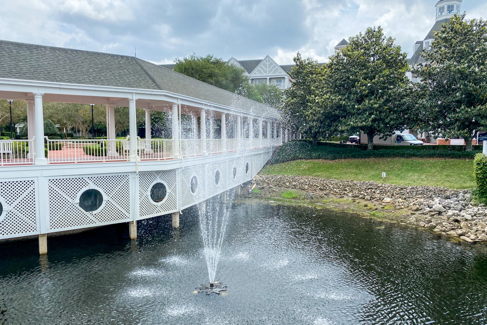
Not only is walking to two parks a considerable benefit, but the hotel resides on beautiful Crescent Lake . So it’s one of the most pleasant places to take a leisurely stroll at Walt Disney World.

If you plan to spend a decent amount of time at Epcot or Hollywood Studios, I strongly suggest considering any resorts within walking distance of the parks . Other resorts in this area include:
- Disney’s Beach Club Resort
- Disney’s Boardwalk Inn
- Disney’s Swan and Dolphin Resort
Another reason I love this area is that it provides teens with a great place to roam without worrying too much. When my son turned 14 (the age at which you can enter a park without an adult), he loved that I gave him some freedom to walk over to the nearby parks. Additionally, Epcot has multiple festivals throughout the year. If you plan a vacation primarily to visit any of the festivals, Disney’s Yacht Club is an excellent hotel option.

Disney’s Yacht Club has a classic interior with elements like sailboats, knots, and leather mixed with pretty shades of blue and gold. Modern furnishings were added to the lobby during its latest refurbishment.

You might even catch a glimpse of a giant hidden Mickey in the central rug. It’s the largest one I’ve encountered.

A massive globe, the lobby’s centerpiece, sits prominently on display.

On this visit, we were in room 2126, which was only a short walk down the second-floor hallway. We enjoyed walking out of our room and down the stairs to the lobby so quickly.

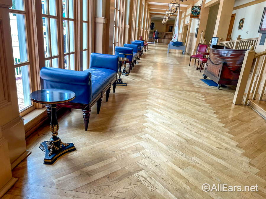
There’s a small sitting area at the top of the stairs if you want to enjoy a more private space.

You might also notice the carpet is on point. No pun intended. It features a compass pattern.

Our Room at Disney’s Yacht Club
Disney’s Yacht Club is slightly different from the other deluxe resorts regarding accommodations. It’s the only upscale resort that doesn’t have a separate Disney Vacation Club.
However, next door, Disney’s Beach Club is home to the Beach Club Villas, a Disney World Villa Resort . All of the villa resorts are Disney Vacation Club (DVC) Resorts.
Related: Disney’s Beach Club Villas Review
Most of Disney’s Yacht Club rooms sleep up to five guests. However, club level rooms usually sleep four guests. We have an entire article covering the experience if you’re curious about club level.
Related: Club Level at Disney’s Beach Club
Here are the following room view categories at Disney’s Yacht Club:
- Standard View (Roof or Parking Lot View)
- Garden or Woods View (View of Gardens)
- Water View (View of Crescent Lake or Stormalong Bay)
Additionally, the Yacht Club has several two-bedroom suites for those needing a larger space. Those suites sleep up to six guests.
We booked a standard guest room with a garden or woods view for this stay. Our room had two queen-size beds and a futon-style sleeper.

Some rooms have king-size beds with a daybed. However, those rooms are usually considered an upgrade.
Rooms at Disney’s Yacht Club have solid surface flooring that resembles hardwood. Here is the fold-down sofa that converts to a fifth sleeper.

Our guest bath was split with a separate vanity area from the water closet. There were two sinks, and our bath had a tub with a shower combination.

While our view was private, there wasn’t anything outstanding about it.

In the past, we’ve stayed in a water-view room at Disney’s Yacht Club. This is my all-time favorite room view at Walt Disney World, and I’ve stayed at many resorts.

I enjoyed this view so much that I woke up every morning and sat on the balcony. During the day, we would visit the parks for a bit before coming back for a break. My first thought upon entering the room was to head out to the balcony.
We would get ready for dinner in the evenings and enjoy a drink on the balcony before leaving. Then, when we returned to the room after dark, we would enjoy the view of the fireworks from Epcot.
I could have sat there all day and indulged in the comings and goings below.
Overall, the guest rooms at Disney’s Yacht Club are relatively simple and modern. Beds are platform-style, which allows room to store luggage underneath. One of the items that I liked the most was the curtains. They feature Disney-inspired constellations.

In addition, our room had a built-in closet across from the bath area with a safe, coffee maker, and mini-refrigerator. We have a separate article that features a video tour of the room and photos of all the details.
Related: Room Tour of a Standard Guest Room at Disney’s Yacht Club

Dining Options at Disney’s Yacht Club
When it comes to dining at Disney’s Yacht Club, there are plenty of options at the resort and within the nearby area. However, all of the resorts in the area are lacking when it comes to counter-service options.
The Market at Ale and Compass
The Market at Ale and Compass is the primary counter-service dining option at Disney’s Yacht Club. Unfortunately, most of the items are pre-made, which is not a good look for a high-end hotel.
Related: The Market at Ale and Compass

During our stay, I stopped for a few updated photos. But not much has changed from our last visit.

Plenty of chips, candies, and allergy-friendly alternative snacks were available.

Here is the refrigerated case with various bottled waters, beverages, soda, juice, and pre-packaged meals.
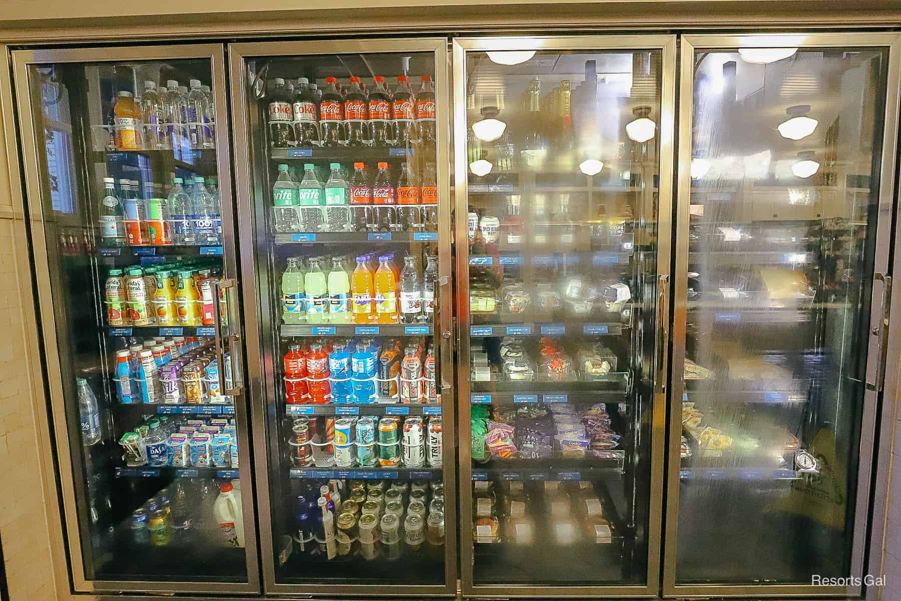
There’s a case with several novelty ice cream treats toward the back. To the left of the case, there’s a microwave for anyone to use.

Disney Rapid Fill Mugs are available for purchase at The Market. At the time of this review, they are $21.99 for the entire length of your stay.

Additionally, The Market at Ale and Compass has a decent coffee bar. Here are a few of the available items.

You can preview the full breakfast, lunch, and dinner menu here on Disney’s site. Below is a photo of the dining area inside the counter service.

Ale and Compass Lounge is located off the resort lobby. This location offers a small appetizer menu with a fairly unique selection of cocktails. We often enjoy stopping in for an order of Parker House rolls.
Related: Ale and Compass Lounge Review

Ale and Compass is one of our favorite restaurants at Disney’s Resorts. Not only does this location serve one of the best breakfasts at Disney, but it also serves lunch and dinner. Plus, they have a to-go menu on the mobile-order portion of the My Disney Experience app.
We had breakfast one morning during this stay, and I had the Salted Caramel Apple French Toast. It was divine. But as you already know, my favorite item here is the chocolate waffle.
Related: Ale and Compass Breakfast Review

We’ve had everything from the Vermont Cheddar Burger to the Fish with Fries for lunch and dinner.
Related: Ale and Compass Lunch and Dinner Review

Crew’s Cup Lounge is located down a hall off the Yacht Clubs’ lobby. This location serves as the lounge for Yachtsman Steakhouse.
Don’t skip out on this location, thinking it’s just “another lounge” because it’s not. Crew’s Cup doesn’t require reservations and has a full menu with food and beverage options.
On this visit, we stopped in to try the charcuterie board. It was delicious and more than enough for two people to share.
Related: Crew’s Cup Lounge at Disney’s Yacht Club

Yachtsman Steakhouse
Yachtsman Steakhouse is the signature dining location at Disney’s Yacht Club. We’ve had the opportunity to dine here several times in the past.
Yachtsman specializes in serving prime cuts of beef. You will pass a butcher-style display of said meats on your way to the table.
However, the best part about dining at Yachtsman Steakhouse? Onion rolls. They are delicious, and the server will bring roasted garlic to the table to enjoy with them.
Related: Yachtsman Steakhouse Review

Hurricane Hanna’s
Lastly, we have Hurricane Hanna’s, a walk-up waterside bar and grill that services Stormalong Bay, the pool area. This counter service location offers burgers, chicken nuggets, sandwiches, and similar items.
Related: Hurricane Hanna’s Review

Additionally, you might enjoy a meal at one of these restaurants located on the Beach Club side of the resort:
- Beaches and Cream Soda Shop
- Beach Club Marketplace
- Cape May Cafe (Character Breakfast)
- Cape May Cafe Seafood Buffet
- Martha’s Vineyard
We also have a complete guide that lists the options at both resorts.
Related: Restaurants at Disney’s Yacht and Beach Club
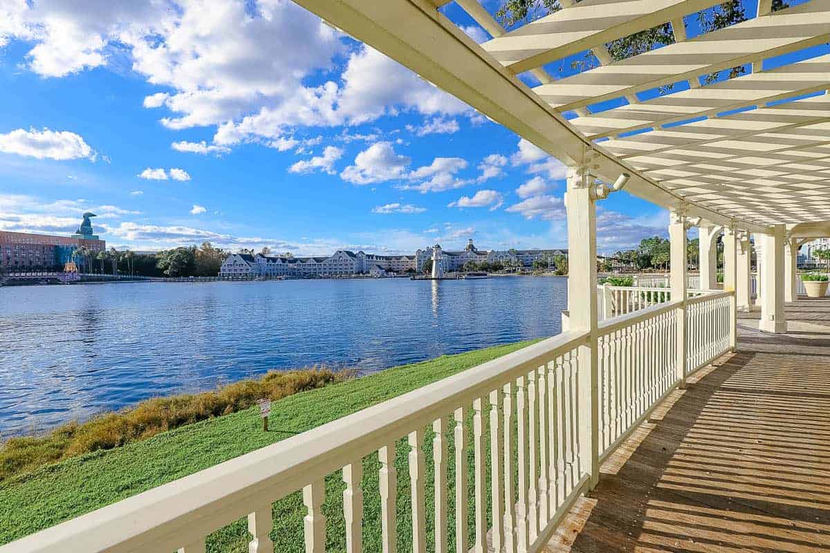
In addition to its location, the Yacht Club has one of the best pools at Walt Disney World . Stormalong Bay is a huge feature pool that’s more of a water park than a pool.
Stormalong Bay has the following: a lazy river, a water slide, a sand bottom pool, multiple hot tubs, a kids’ pool, and much more!
Related: Everything You Need to Know for Stormalong Bay

We always plan an entire day at Stormalong Bay during our visits. We checked into the hotel early for this trip to spend the day at the pool.
Since our room was ready upon arrival, we were able to put our things away and then head directly out to the pool. However, a large bathroom behind the pool has a changing area for guests.
Additionally, there’s a shower with toiletries for guests. So if you have a late flight, you could spend the day at the pool. Then you could shower and change before heading to the airport.

There’s one other thing I wanted to mention about the pool. Yacht Club’s water slide sits across the walkway from the pool area at the top of the shipwreck.
Sometimes, guests complain that children have to leave the pool area to enter the water slide. However, I’m sure most guests are unaware that there’s a kiddie pool inside the shipwreck. It’s a hidden surprise to those who dare to take on the Flying Jib water slide.

We splurged on a cabana rental at Stormalong Bay on a previous visit. While the cabana rental was pricy, it was an experience we won’t soon forget. We have a separate article that details our day.
Related: Poolside Cabana Rentals at Disney World

Outside the pool area, several beaches are available with chairs and swings. Below is a fire pit where marshmallows are roasted each evening. Additionally, Movies Under the Stars are usually held in this area on the beach when it’s warm.

There should be several activity schedules posted around the resort.

These schedules list the times for the campfire, poolside activities, crafts, and other various recreational items. Toward the bottom, it lists the nightly movie schedule. It was cooler in the evenings during our stay, so movies were being held at the Beach Club’s Solarium.

Guests looking for a more private relaxing spot at the Yacht Club will enjoy the resort’s quiet pool, the Admiral Pool.
Related: The Pools at Disney’s Yacht and Beach Club

It has a whirlpool spa.

There is even a tennis court.

Additionally, the resort’s main laundry facilities are located near the quiet pool. So, if you need to do a little laundry, this is an excellent location. Usually, I like to start our laundry, then grab a bite to eat and enjoy a peaceful lunch by the pool.
Related: Laundry Facilities at Disney’s Yacht Club

Disney’s Yacht Club is home to Bayside Marina. The marina offers motorized boat rentals that you can reserve in advance.

This is also the location to meet for Epcot’s fireworks cruises.

Disney’s Yacht Club has a fitness center called Ship Shape Health Club. It sits directly behind Stormalong Bay and is shared with the Beach Club. Ship Shape is a convenient facility that offers anything needed to get a good workout while on vacation. In addition, the gym has cooling towels and a place to refill a water bottle.
Related: Fitness Centers at Disney World

If you prefer to run outside, there’s no better place than the running trail around Crescent Lake. You’ll run into several trail maps around the resort during your stay.
Related: Best Jogging Trails at Disney World

Lastly, Disney’s Yacht Club shares an arcade with the Beach Club. Lafferty Arcade sits next door to the Ship Shape Health Club. Here is a look inside.

As we discussed earlier, the Yacht Club’s location is one of the resort’s most significant benefits. In addition to being able to walk to two parks, the resort offers boat and bus services. Yacht Club has a dock right outside its back door at the lighthouse. Disney’s Friendships boats provide transportation to the surrounding resorts, Epcot, and Hollywood Studios.
Related: Disney’s Friendship Boat Service

If you prefer to walk, Epcot is less than 10 minutes away. For Hollywood Studios, the walk takes approximately 15-20 minutes. Walking on the way back to the resort is a great way to decompress after visiting the parks. Guests traveling to the following theme parks and destinations will want to take a bus from the Yacht Club.
- Magic Kingdom
- Animal Kingdom
- Disney Springs
- Blizzard Beach
- Typhoon Lagoon
Yacht Club’s bus stop is outside the resort’s main entrance.

Both resorts (Yacht and Beach) share bus service, so don’t be surprised if your bus stops at Beach Club before heading to your destination. Yacht Club is the first stop upon return. Guests can also walk to the International Gateway or Hollywood Studios to use the Skyliner gondola transportation. This is a great option for anyone visiting Caribbean Beach or Disney’s Riviera Resort for a meal. For more information, we have a guide with tips on the best way to get to and from the Yacht Club.
Related: Disney’s Yacht Club Transportation Guide

Resorts Gal’s Spin on Disney’s Yacht Club
Is a stay at Disney’s Yacht Club worth the price? My answer is that it’s entirely up to your budget. However, if you can reasonably afford to stay at the Yacht Club, I don’t think you’ll regret it.
We love to stay at Disney’s Yacht Club because we enjoy the classy style of the resort, the pool, and the location. It’s our vibe. That said, Disney has a ton of excellent deluxe resorts that might be more what your idea of a vacation is than mine. All of the great options can make the decision difficult.
For example, while I love the Yacht Club for its location, you might enjoy a resort like Disney’s Polynesian. It has a tropical Hawaiian feel that you might consider more relaxing. ( Disney’s Polynesian Resort Review )
Another favorite is the Animal Kingdom Lodge. While this is not my favorite resort, it ranks as our choice for the best resort at Walt Disney World due to its uniqueness. ( Disney’s Animal Kingdom Lodge Review ) Additionally, we love to stay at Disney’s Contemporary Garden Wing . However, the Contemporary is not for everyone.
Final Thoughts
We hope this review of Disney’s Yacht Club provided an overview of whether or not the resort will work for your family. We love staying at both the Beach and Yacht Club. Even during this most recent stay, I thought about how I’ve never tired of staying here. These are also the resorts I almost always compare with other hotels.
As someone fortunate to travel often, I always eventually get a little homesick for this place I love dearly. Some of the days we’ve spent at Stormalong Bay are my best Disney memories. I hope you’ll enjoy it as much as I do.
Wrapping up this Disney’s Yacht Club review, I wanted to add a few points to remember about the resort.
- Staying at Disney’s Yacht Club offers the opportunity to save a considerable amount of travel time between two parks. Additionally, the ease of being close to Galaxy’s Edge at Hollywood Studios and Guardians of the Galaxy: Cosmic Rewind at Epcot only add to the convenience.
- Since Yacht Club is a Disney Resort, resort guests are eligible for early theme park entry .
- Resort guests of the Yacht Club will also have access to extended evening hours for deluxe resort guests.

For more nearby Disney World Resort Reviews , try these articles:
- Disney’s Swan and Dolphin Review
- Disney’s Boardwalk Inn Review
- Disney’s Riviera Resort Review
- Disney’s Caribbean Beach Review
- Disney’s Coronado Springs Review
In the comments
What do you think of Disney’s Yacht Club Review? Have you had the chance to stay at this resort? Do you hope to stay here in the future, or do you have any reservations about the resort?

Hi, I'm Amber the owner of Resorts Gal . We have stayed at every single Disney Resort Hotel. Our philosophy? We believe you can have an incredible time at the resorts without ever setting foot in a theme park. We live near the parks and visit weekly and would love for you to follow along.
Leave a Reply Cancel reply
Your email address will not be published. Required fields are marked *
Save my name, email, and website in this browser for the next time I comment.
Disney’s Yacht Club Resort Review
Hoping for a chic place to stay at Disney World where the kids can still feel at home? At Disney’s Yacht Club Resort, sophisticated style, refined restaurants, and an epic hotel waterpark make for the perfect stay for families and couples alike.
So, how does the Walt Disney World Yacht Club Resort compare to the other deluxe hotels? Is this spendy stay worth the price of admission? Grab your captain’s hat and a compass as we set sail to find out. (Updated September 7, 2022)

Staying at the Disney World Yacht Club Resort
Yacht clubs may typically be for the rich and famous, but you don’t need to be the owner of a swanky ship to stay at Disney’s Yacht Club Resort. Overlooking Crescent Lake towards Disney’s BoardWalk , it’s the more dignified stay of the Disney Yacht & Beach Club Resorts, perfect for an adult Disney trip , kid-friendly perks like the best Disney hotel pool, and a convenient location in the middle of the Epcot & Hollywood Studios Resort Area .
With quaint grey buildings trimmed in white and a lighthouse guiding Friendship Boats to the marina, this deluxe resort is styled like a stately yacht club along New England’s coastline. Only a short walk from the International Gateway entrance at Epcot with a covetable spot on the Disney Skyliner route, it’s an ideal stay for families hoping to maximize their time at Hollywood Studios or adults stumbling back to the room after a day spent drinking around the world .
Disney World Yacht Club Rooms & Suites
The Walt Disney World Yacht Club Resort touts a 4.5 on TripAdvisor. As with other deluxe resorts at Disney World, it has a variety of room types to choose from including standard rooms, Disney club-level rooms , and even a 2-bedroom suite. If you’re picky about the view and don’t want to get stuck with uninspired scenes of the resort’s rooftops, choose from a relaxing garden-view or water-view room instead.
A far cry from the outdated, on-the-nose guestrooms of the past, rooms here use more contemporary elements like dark woods, strong lines, crisp linens, and nautical touches for a more refined take on classic coastal style. With sky-chart-inspired curtains, a mirror reminiscent of a porthole, and a feature wall with menswear flair, a stay here feels like stepping into the captain’s quarters on a posh mega yacht.
In general, all standard rooms and suites at the Yacht Club come with the following amenities: a hairdryer, iron, ironing board, mini-refrigerator, coffee maker, in-room safe, telephone with voicemail, and free Wi-Fi.
Standard View Room
- Comes with 1 king bed or 1 king bed & 1 day bed or 2 queen beds & 1 day bed or 1 queen bed & 1 day bed & 1 twin-sized sleeper chair
- Sleeps between 2 to 5 adults
- Views of the parking area or resort rooftops
Garden or Woods Room
- Comes with 1 king bed or 2 queen beds or 2 queen beds & 1 day bed or 1 queen bed & 1 day bed & 1 twin-sized sleeper chair
- Views of the gardens or forested areas
Water View Room
- Comes with 1 king bed or 1 king bed & 1 day bed or 2 queen beds or 2 queen beds & 1 day bed or 1 queen bed & 1 day bed & 1 twin-sized sleeper chair
- Views of Crescent Lake or the quiet pool
2 Bedroom Suite
- Comes with 2 king beds and 1 queen-sized sofa sleeper
- Sleeps up to 6 adults
- Views of Crescent Lake or Stormalong Bay
Rooms with Club-Level Service at the Walt Disney World Yacht Club
Club-level guestrooms at Disney’s Yacht Club offer the same handsome interiors and thoughtful amenities (see above for details) as the standard rooms and suites, plus a DVD player, as well as the following benefits at the Regatta Club: complimentary access to the health club, complimentary fax assistance, complimentary newspapers in the Regatta Club, evening turndown service, and access to Disney Signature Services and a personalized front desk. Club-level guests are also able to access the Regatta Club with their key when refreshments are served between 7 AM and 10 PM.
Standard View – Club Level Room
- Comes with 1 king bed or 2 queen beds
- Sleeps between 2 to 4 adults
Garden View – Club Level Room
- Comes with 1 king bed or 2 queen beds or 2 queen beds & 1 day bed
- Views of the gardens
Water View – Club Level Room
- Comes with 1 king bed or 1 king bed & 1 day bed or 2 queen beds or 2 queen beds & 1 day bed
- Views of Stormalong Bay
Disney Yacht Club Resort Prices
Ready to book your reservation at the Walt Disney World Yacht Club Resort? You’re probably wondering how much it’ll cost you to stay there. With sophisticated rooms, an unbeatable location, and arguably the best hotel pool at Disney World, a night here doesn’t come cheap.
In fact, even if you stay in the most basic room of the bunch during the slowest time of year, you’ll still end up dropping at least $500 a night. So, if you’re traveling on a shoestring, one of Disney’s All-Star Resorts might be more your speed. Or save on your hotel stay without skimping on little Disney luxuries, stay at one of the charming Disney Port Orleans Resorts or another moderate resort instead.
If you’re ready to treat you and your loved ones to a stay at Disney’s Yacht Club, room rates will depend on a few different things like what time of year you’re traveling, how many people are staying, and what you want to see when you look out your window. For example, while watching the Christmas fireworks from your water-view room on the Regatta Club level will run you almost $1,400, staying during the slow season in a room with a less-than-picturesque view of the roof will net you around $900 in savings .
With rates spanning from the mid-$500s during the slow season to the mid-to-high $900s, basic standard-view rooms without access to the Regatta Club are the most affordable option. Contrastingly, if your clan is large or you’re looking to splurge, prices for a 2-bedroom suite with keys to the club-level lounge start in the low $2,000s and top out in the high $3,000s.

Below are some examples of room rate ranges for stays in 2023 , arranged by starting price, for each of the room types available at the Yacht Club (expect slightly lower rates in 2022 ) :
- Standard View Room: $542 to $986
- King Bed: $549 to $991
- Garden or Woods View Room: $586 to $1,034
- Water View Room: $684 to $1,118
- Standard View – Club Level: $796 to $1,378
- Garden View – Club Level: $828 to $1,398
- Water View – Club Level: $939 to $1,566
- 2 Bedroom Suite: $2,182 to $3,877
Disney Yacht Club Hotel Amenities
Although room rates at Disney’s Yacht Club are on the spendy side, as a deluxe resort , you’ll have access to some of the best hotel amenities on Disney property. Unlike staying at Disney’s Art of Animation or one of the other value resorts, there are more than enough things to do at the Yacht Club at Walt Disney World to keep you entertained all vacation long.
Disney Yacht Club Dining
Just like the elegant yacht clubs that dot the New England coast and the rest of the United States, Disney World’s Yacht Club Resort offers an array of tempting dining options. As this is one of the more grown-up resorts at Walt Disney World, don’t expect any seafaring-themed Disney dinner shows or character dining starring Donald Duck in his iconic sailor outfit here. Instead, you’ll find everything from a grab-and-go market to a prime steakhouse.
Best of all, with the Beach Club right next door and Disney’s BoardWalk only a short stroll away, you’re minutes away from a smorgasbord of other Disney World restaurants that are perfect for pleasing even the pickiest of eaters.
Ale & Compass Lounge
Attached to the table-service restaurant of the same name, the Ale & Compass Lounge is a distinguished spot to grab a drink after a long day exploring the parks. With its dark blue paneling, plush furniture, and tin ceiling accents, you almost feel as if you’re in a classy cruise ship lounge. Stop by for elevated appetizers like Lobster and Corn Chowder and a Bacon and Vermont Cheddar Burger; stay for the old-school and updated craft cocktails .
Ale & Compass Restaurant
With both a to-go menu and a handsome, expansive dining room, the Disney Ale and Compass Restaurant is a welcome stop whether fueling up for a day of adventures or dropping anchor after hours in the parks. Serving up both breakfast and dinner, this table-service restaurant styled after an inviting lighthouse is a beacon for hungry guests both day and night.
In the morning, tuck into seaside breakfast favorites like Shrimp and White Cheddar Grits, Crab Cake Benedict, or a Maine Lobster Roll. At dinnertime, dig into a selection of comfort food classics with a coastal twist like New England Seafood Pot Pie and Short Rib “French Dip” Flatbread.
Crew’s Cup Lounge
With its warm wood beams, Craftsman-style elements, and a convenient location next door to the Yachtsman Steakhouse, Disney’s Crew’s Cup Lounge is a cozy place for a drink before heading to dinner or on your way back to the room. While you could just come for a glass of wine or a boozy coffee cocktail, this hotel bar also offers an extensive menu with dishes from the neighboring steakhouse, making this an excellent alternative if you can’t score a reservation.
The Market at Ale & Compass
Serving up breakfast, lunch, and dinner – as well as a substantial selection of Disney souvenirs, snacks, and sundries – The Market at Ale & Compass is the place to go for a fast meal at Disney’s Yacht Club. This quick-service restaurant serves up pretty standard AM fare such as Mickey Waffles and breakfast sandwiches in the morning before transitioning to light bites like sandwiches and salads in the afternoons and evenings.
Yachtsman Steakhouse

No yacht club in the Hamptons is complete without a ritzy steakhouse slinging surf-and-turf favorites. Warm and welcoming with seaworthy touches like knotty pine and porthole-inspired windows, the Yachtsman Steakhouse feels more laidback than stuffy, although a dress code is required (no flip-flops here!).
Cut into carnivorous classics like the 28-oz Porterhouse for Two or the Roasted Prime Rib or stick to fresh-from-the-sea fare like Seafood Cioppino or a Chilled Admiral’s Tower for Two overflowing with lobster, crab, mussels, and more. End your meal on a sweet note with desserts like Yachtsman’s Chocolate Cake or Crème Brûlée.
Disney Yacht Club Pools
Like to get in the water as much as you like to get on the water? Well, you’ve come to the right place. One of the resorts with the best hotel pools at Disney World , Yacht Club is home to the only waterpark at a Walt Disney World hotel: Stormalong Bay. Sprawling across 3 glorious acres on the shores of Crescent Lake, this aquatic paradise is the perfect spot for a beach day – no trip to the coast necessary.
New Immersive Suites Come to Life in Paris Disneyland Hotel

Splash down the 230-foot-long waterslide, let your cares drain away along the lazy river or in one of the whirlpool spas, sink your toes into the sand-bottomed pool, or even discover the ruins of the resort’s resident shipwreck. Yachting is all about luxury, so splurge on a full-service cabana for you and your crew (reservations required).
As you can imagine, Stormalong Bay can get pretty busy during the day. To skip the crowds, try visiting one of the 3 different leisure pools shared by Disney’s Yacht & Beach Club Resort.
Other Recreation at Disney’s Yacht Club
The WDW Yacht Club Resort may be the Disney hotel with the best pool, but there are plenty of other recreational activities to keep you busy all vacation long. While you don’t need the keys to your own Sunseeker to gain entrance to Disney’s Yacht Club hotel, you can rent some out by the half-hour for everything from a 2-person Sea Raycer to a 10-person pontoon boat from the resort marina – one of our top things to do outside the theme parks . Or for other on-the-water fun, go on a guided fishing excursion or pirate adventure cruise instead.
Rather keep both feet on dry land? The youngest resort guests will love watching some of their favorite Disney flicks during Movies Under the Stars or toasting marshmallows around the campfire, while grown-ups can keep their exercise routine intact on the jogging path or during an intense match on the volleyball or tennis courts.
Getting cabin fever? Take some time to explore the resort’s incomparable location. The Disney World Yacht and Beach Club is just a short walk from the tasty restaurants, entertaining nightlife, and turn-of-the-century appeal of Disney’s BoardWalk complex. Or for wholesome thrills the whole family can enjoy, work on your swing at Disney’s Fantasia Gardens Miniature Golf Course across the street from the Walt Disney World Swan & Dolphin Resorts.
Disney Yacht Club Merchandise Locations
For those searching for that perfect souvenir, set a course for The Market at Ale & Compass. This one-stop shop is a convenient spot to pick up forgotten essentials, Disney merchandise, and provisions for a day in the parks. As the location of the resort’s quick-service restaurant, table-service restaurant, and to-go outlet, it’s also an ideal pitstop before cruising to the parks or back to your room.
Disney Yacht Club FAQs
Want to know more about Disney’s Yacht Club Resort? Read on for answers to some commonly asked questions.
Is Disney Yacht Club kid-friendly?
Yes! Despite the more grown-up vibe, Disney’s Yacht Club can be a great place to stay for families with children of all ages. While the guestrooms aren’t exactly overflowing with pixie dust, you’ll still find plenty of kid-friendly activities to keep little ones feeling the magic, from splashing around in Stormalong Bay to watching Disney Movies Under the Stars. And if there aren’t enough options to please the picky eaters in your life at the Ale & Compass, there definitely will be at Beaches & Cream Soda Shop next door at Disney’s Beach Club.
When was Disney Yacht Club refurbished?
Rooms at Disney’s Yacht Club Resort were renovated rather recently in 2017, a welcome update from the previous guestrooms’ dated design touches like nautical headboards and white-painted furniture.
Can you see fireworks from Disney Yacht Club?
Yup! While you won’t be able to watch the entire show, thanks to its covetable location in the heart of the Epcot and Hollywood Studios Resort Area, you will be able to catch some of the higher fireworks from both nighttime spectaculars. In fact, aside from the beach at Disney’s Polynesian Village Resort , it’s also one of our top spots to watch the Disney World fireworks outside the parks . Just head to the resort’s lighthouse on Crescent Lake. If you’re lucky, you may even be able to catch glimpses of the show from the comfort of your hotel room.
Can you walk from Yacht Club to Hollywood Studios?
Yes! If you’d rather not take the bus, Friendship Boat, or Disney Skyliner , there is a walking path that connects the Epcot Resort Area to Disney’s Hollywood Studios. Roughly 1-mile long or around a 15 to 20-minute walk, the walkway runs from between Disney’s BoardWalk Inn and the Walt Disney World Dolphin Resort to the main entrance to Hollywood Studios.
How long is the walk to Epcot?
Walking to the International Gateway entrance at Epcot from Disney’s Yacht Club Resort will only take around 10 to 15 minutes depending on your pace. If you’re not in a hurry, you can also enjoy a leisurely 20-minute ride from the hotel to the park on one of the Friendship Boats .
How long is the bus ride from Yacht Club to Magic Kingdom? Animal Kingdom?
Taking the Disney bus from the Yacht Club to Magic Kingdom typically takes around 20 minutes, as does the bus to Animal Kingdom . If you’ve really got some time on your hands and are looking to take the scenic route, you can also take the Monorail from the front of Epcot to Magic Kingdom Park.
However, as you will need to walk all the way through World Showcase and Future World just to reach the Monorail, this hourlong route definitely isn’t for the faint of heart or those short on time. Keep in mind that you will need a park ticket (and currently, also a park reservation) to get to the Epcot Monorail from Disney’s Yacht Club.
Well, crew, that concludes our cruise around Disney’s Yacht Club Resort. With its adult ambiance, convenient location, classy style, delicious restaurants, and a boatload of recreational activities (including the best hotel pool at Disney World), it’s an excellent choice for everyone from families with children (especially older kids and teens) to couples.
While you’re there, make the most of your time at the resort’s two closest parks with our 1-day plans for Epcot and Hollywood Studios . Or since you indulged in a deluxe resort, why not save some cash with our discounted Walt Disney World tickets .
Have you ever stayed at Disney’s Yacht Club? Which room type or restaurant is your favorite? Is the Regatta Club worth it? Where is the best place to watch the Epcot fireworks ? Let us know in the comments!

Disney Yacht Club Resort Review
W e love the Boardwalk area at Disney World and are always on the lookout for a good deal at one of the resorts in that area. Being able to easily walk to both EPCOT and Hollywood Studios is a huge plus for us. And we can finally say we have officially stayed at every resort on Disney’s Boardwalk! Disney’s Yacht Club Resort has been on our radar for some time now and we recently had the opportunity to stay at this resort and experience everything it has to offer. Read on for our full Disney Yacht Club Resort Review!
Yacht Club Resort at Walt Disney World
Yacht Club is a deluxe resort at Walt Disney World that is situated in Disney’s Boardwalk area, near EPCOT. With an elegant New England style Yacht Club theme, this nautical resort is the perfect place to relax and unwind. While its sister resort, Disney’s Beach Club, is known more for its beachy, cottage type feel, Yacht Club transports you to a place that feels like luxury.
Home to several restaurants and the Stormalong Bay pool complex it shares with Beach Club, let’s take a look at this resort and see if it’s right for your next Disney Vacation.
Yacht Club Resort Atmosphere
The atmosphere is Yacht Club is laid back but feels slightly more elevated and upscale than Disney’s Beach Club. Some think it feels a bit “stuffy”, but it’s nowhere near as sophisticated as say, Disney’s Grand Floridian Resort. The resort feels nautical. And has the lovely scent of Green Clover and Aloe filling the lobby and hallways.
Since Yacht Club doesn’t house any character meals and is slightly farther from EPCOT than Beach Club, it’s often quieter and less chaotic feeling in general as well.
Yacht Club Resort Rooms
The rooms at Yacht Club resort are modern and simple. They have small Disney details. But nothing that is in your face Disney. One of the best parts about the rooms at Yacht Club is that they sleep five. Much like the rooms at the Contemporary, these rooms include two queen beds and a couch that converts into a twin bed. The twin bed is large enough to fit a small to average sized adult. So this makes them great for families needing a little extra space. Or for larger parties that don’t want to splurge on a family suite or villa.
The Yacht Club rooms have the classic room and bathroom setup. The vanity area is able to be closed off from the rest of the room by closing the door. And the toilet and shower are also able to be separated as well.
We booked a resort view, which can mean a variety of things and were pleasantly surprised at our view! See above for photos from our balcony. We could see EPCOT’s fireworks from our balcony and that felt like a huge added value, as we happened to be traveling during January for this trip. Which meant that we often had earlier nights in.
The Yacht Club Resort’s rooms feel spacious, clean and updated. And though there’s not a ton of Disney theming, if you look closely, you can see some very cute Disney touches that match the decor. Hidden mickeys in the photographs. And Disney characters in the shape of constellations on the curtains.
Yacht Club Resort Grounds
The resort grounds at Disney’s Yacht Club are fairly limited to the Boardwalk area . With palm trees and white sandy beaches that it shares with Disney’s Beach Club Resort , and its amazing pool, Stormalong Bay, the actual resort is quite compact. This makes getting around super easy. Though Yacht Club does have tennis courts and some green space, it’s not an expansive resort by any means.
Disney Yacht Club Resort P ools
The pool at Disney’s Yacht Club is the main attraction. And one reason so many people are willing to pay the cost to stay here. It really is the best pool at Walt Disney World. With a sandy bottom, lazy river, very cool pirate ship slide and plenty of room, both for swimming and for lounging, you could come to Disney just for the pool and be happy.
There is also a pool bar, Hurricane Hannah’s, that offers drinks and small plates. You can order these from one of the servers at the pool area. Or walk up to the counter and order that way.
The pools at Yacht and Beach are pretty strict when it comes to who can use them. Guests are required to scan in with a cast member before being allowed to enter. And will receive a wrist band at the gate to prove that they’re allowed to be there.
Disney’s Yacht Club also has a quiet pool called the Admiral Pool, located around the back of the resort near the tennis court.
Does the Beach Club and Yacht Club Share Pools?
Yes they do! Stormalong Bay is the main attraction here. And is one of the reasons the two resorts are so popular. Guests of the Beach and Yacht Club Resorts share the pool at Stormalong Bay, and you do need to scan in with a cast member to use the pool.
Yacht Club Transportation Options
Transportation at Yacht Club is fairly simple and straightforward. They have ferry service that goes from the Yacht Club to both EPCOT and Hollywood Studios, as well as the resorts in the immediate area. You can take Disney’s Skyliner to Hollywood Studios or any of the Skyliner Resorts . And you can also walk to the back entrance of EPCOT to enter at the International Gateway and walk to Hollywood Studios via the walking path .
Disney busses will take you to Magic Kingdom, Animal Kingdom and Disney Springs. The buses are usually shared between Yacht Club Beach Club and Boardwalk Inn, so be aware that you may want to account for extra time when traveling to these locations.
Yacht Club Dining and Restaurants
One of the biggest challenges with staying in a Boardwalk area resort is finding hot food on the go. Neither Beach or Yacht Club have a full kitchen in their quick service locations, so hot food options are very limited. Yacht Club does do a little better here though, as they have hot breakfast sandwiches and Mickey waffles. And we love that you can get specialty lattes and coffees here as well.
Ale and Compass
Ale and Compass is the main restaurant at Yacht Club Resort. Though there are always mixed reviews of this place, we love the chocolate waffles. And feel it’s one of the best breakfasts you can get at Disney for $15. We have seen inconsistency be an issue at Ale and Compass, especially when it comes to the flatbreads. But overall, we enjoy this restaurant and love that you can get food to go!
Ale and Compass Lounge
If you’re looking for a lounge with an upscale feel, great drinks and service and some delicious bites, look no further than Ale and Compass Lounge. We are big fans of this lounge at Disney World. And even come here on days when we aren’t staying in the area but just need a break from EPCOT.
You can find the full menu for Ale and Compass Lounge here .
The Market at Ale and Compass
The Market at Ale and Compass is the resort’s quick service commissary. This is where you’ll find grab and go foods, specialty coffees and where you can fill up your refillable mug or grab a soft drink. One thing that’s hard to ignore is that it’s sometimes difficult to find good hot food to go in this area of the Boardwalk. Or really, on most of the Boardwalk in general. There are plenty of grab and go options for colder food like premade treats, sandwiches and salads. But if you want something made fresh and hot, your options will be a bit more limited.
We think the Market at Ale and Compass tends to do just a little bit better than Beach Club with its hot offerings. But you won’t find a full hot menu here like you would at most of the other resorts.
Yachtsman Steakhouse
Yachtsman Steakhouse is Yacht Club’s upscale restaurant. Serving steaks, seafood, chicken and more, this is a perfect place for a date night, or any other time you’re looking for a special meal. We’ve never eaten here before mostly because it’s quite pricey. That being said, if you’re a steak lover, this place gets great reviews and is worth looking into for a special occasion.
Crew’s Cup Lounge
Crew’s Cup Lounge is a full bar, located right next to Yachtsman. Many people stop by here before heading to the steakhouse for pre-dinner drinks, but you don’t have to be a guest of the restaurant to visit. While Ale and Compass serves brighter and lighter flavors, Crew’s Cup is big with the Scotch crowd. If you’re looking for Scotch at Disney, this is the place to go. They also have a wide variety of coffee cocktails if that’s your thing, and a few options for small plates as well.
You can see the full menu for Crew’s Cup Lounge here .
Gift Shop at Yacht Club
The gift shop at Yacht Club is a bit more upscale than you’re probably used to for a Disney resort. Not only do they carry the standard Disney apparel, mugs and souvenirs, but they also carry high end brands like Vineyard Vines and sometimes Lilly Pulitzer. They are located in the right side of the Market at Ale and Compass.
Movies Under the Stars at Yacht Club Resort
We love Movies Under the Stars at Disney ! And we especially love it at Yacht Club because of its location here. Movies Under the Stars here is shared with Beach Club. And is usually shown on the beach near the Pirate Ship Water Slide. During times of inclement weather, it can be held indoors at the Solarium, which is technically located at the Beach Club.
Yacht Club Resort Amenities and Recreation
Disney’s Yacht Club has plenty to do! With an arcade filled with games, resort activities for all ages and of course, their fantastic pool, spending some time at the resort is a great way to spend a non-Park day at Disney.
Fitness Center at Disney’s Yacht Club Resort
Like all deluxe resorts at Walt Disney World, Yacht Club has a fitness center that it shares with Beach Club. Located between the resorts, near the pool and right next to the arcade, this gym has a good variety of equipment including free weights, treadmills, bikes and more.
Laundry Facilities at Disney’s Yacht Club Resort
There are two places you can do laundry while staying at Disney’s Yacht Club. The first is by the Admiral pool. Go past the Marketplace at Ale and Compass and keep walking until you reach the end of the hallway. You’ll find a door leading you to the back of the hotel. The laundry room is by the pool, which can be found right next to the tennis court. There are six washers and dryers here, and it always looks clean and is easy to use.
The second set of washers and dryers is a small room on the first floor, right across from room 1063. This laundry room is likely not the most convenient for many people, but if you’re staying near in this area, it could be nice to not have to go outside to get your laundry done.
Yacht Club Club Level
Club Level at the Yacht Club can be found at The Regatta Club Lounge. This is located on the 5th floor of Yacht Club and can only be accessed with your Magic Band if you’re staying in a club level room. We haven’t experience yet, so we can’t give it a review. But if you’re interested in club level at Disney World, feel free to check out this post !
Map of Yacht Club Resort
How much does disney’s yacht club resort cost .
Prices for Disney’s Yacht Club Resort start at $537 per night for 2024. This is the rack rate, so this is the price you can expect to pay before any discounts or promotions. And often times, you’ll find this much higher depending on when you’re traveling.
Is Yacht Club good for families?
While I do think Yacht Club is good for families, I think Beach Club is likely better for most families. Mostly just because it feels a bit less intimidating. However, both resorts give you access to the main pool, which is the real draw anyway. So yes, this resort is great for families.
Is Yacht Club worth the price?
That depends! We got an excellent price on our room and felt it was 100% worth the price. Between the convenience to EPCOT, the quiet feel, the view from our room and the upscale atmosphere, Yacht Club was worth it for us. Add in the fact that they have by far the best pool at Disney World, and we were very happy with what we paid for it. Keep in mind we traveled here in January, and you can usually find some pretty good deals during this time.
A lot of this will likely depend on what type of Disney experience you appreciate or plan to have. If you’re planning to spend most of your time in the Parks, we rarely feel deluxe resorts are worth it. But if you’re looking for a more relaxing experience, with time to enjoy your resort, it may be worth it for you. In terms of pricing, Disney’s Boardwalk Inn is generally going to be less expensive than Yacht Club, and the more elevated atmosphere may not be for everyone.
We felt this resort was a much better value than Beach Club. Beach Club had a lot of issues when we stayed there including stains in the lobby, tears on the wallpaper in the hallway and it just felt kind of….old and shabby.
Yacht Club feels expensive and we felt that lended a bit more to its price.
Does Disney’s Yacht Club have a fridge?
Nope! All standard rooms, including those at deluxe resorts, only have what is known as a beverage cooler. These don’t get cold enough to hold food that require colder temps for food safety. But they can keep your drinks at a cooler temperature.
Does Yacht Club at Disney have DVC rooms?
They don’t! One of the big differences between Disney’s Yacht and Beach Club is the fact that the Beach Club is a DVC resort, and Yacht Club is not. Disney’s Yacht Club Resort only offers standard rooms.
How far is the walk from Yacht Club to EPCOT?
This will depend on your location in the resort. However, since Yacht Club isn’t that large of a resort, most guests can expect to get the back entrance of EPCOT in about 8-10 minutes. There is also a ferry from the Yacht Club dock that will take you to the same entrance if you prefer to get around that way instead.
Does the Disney Skyliner go to the Yacht Club?
Kind of! Though the Skyliner won’t take you directly to the Yacht Club, you can take Disney’s Skyliner to the back entrance of EPCOT and walk to Yacht Club from there.
Overall, we loved Yacht Club. The food at Ale and Compass and the Market at Ale and Compass was always good, and very easy to get thanks to Mobile Order . The drinks and service at the Ale and Compass Lounge was great. And though we didn’t experience the same welcoming atmosphere at Crew’s Cup, we were fine with it because Ale and Compass is more our style anyway.
Our room was spacious, comfortable and clean. The view from our room was fantastic for a resort view. And we loved being able to see the fireworks from our room. Especially since it was pretty cold during our trip, which meant we usually had a earlier nights.
The bus service is still a point of contention for us, as the buses seem to take forever at this resort. However, since it’s walking distance to Epcot and Hollywood Studios, we rarely used the bus service here anyway.
Would we stay at Yacht Club again?
Yes we would! We would need a very good deal again, as this resort is usually out of our budget. But if the opportunity arose, we would happily stay here again. Though we never thought we’d say this, we prefer the Yacht Club over the Beach Club in terms of theming and atmosphere.
We hope this post has helped you decide if Yacht Club Resort at Disney World is right for you!

Wandering In Disney
A disney theme parks blog.

Yacht Club Resort Review
Disney’s Yacht Club Resort is a deluxe resort in Walt Disney World. Inspired by New England-style architecture, the Yacht Club sits right along the lake. The resort shares many amenities (including the famed pool, Stormalong Bay) and is connected with Disney’s Beach Club. Both the Yacht and Beach Club, along with the Boardwalk Resort make up the Epcot Area Resorts, as they sit just outside of the park’s World Showcase entrance. The Yacht Club is a DVC Resort but also take guests who are not a part of DVC (like me). We recently stayed in a studio room here, this review will cover that experience.

I’d taken many trips to Walt Disney World without staying at the Yacht or Beach Club. One of my favorite unheralded things to do over the years is taking the boat from Epcot to Hollywood Studios, or vice versa. While on this short (and free!) cruise, the boat stops at different hotels. Along with the beautiful Boardwalk, my eyes would always drift to the large ship that seemed to pop out of the Beach and Yacht Clubs. When I realized that this large ship was home to a pool and, more specifically, water slide it was a matter of when, not if, I was going to stay here.
I may like water slides more than an adult should, but the more I read about the Yacht Club the more interested in the resort I became. Disney World’s greatest hotels are a bit like mini theme parks. They each have a theme, things to do and the best ones have a headliner attraction. The Contemporary’s headliner, for example, is the monorail soaring through A-frame. Animal Kingdom Lodge has a savannah outside the backdoor. All Star Sports has groups of raging cheerleaders and youth football players sprinting around the common areas yelling. Kidding about that last one, sort of. The Yacht and Beach Club have a more stereotypical hotel headliner – the pool.
I won’t bury my opinion any further. Staying at the Yacht or Beach Club probably isn’t a wise choice unless there are is at least an hour or two set aside for Stormalong Bay. The large caveat here is that if you have a trip centered around Epcot then this is also a great place to stay but more on that in a minute. The Yacht Club has a nice enough theme. The lobby is on the smaller side relative to other deluxe resorts. The restaurants get solid reviews.

But there is nothing that will blow you away aside from that pool. Stormalong Bay has the aforementioned water slide that is the longest of any WDW resort pool. The pool’s floor is sand, which is one of those things that I didn’t know I loved until I experienced it. There is a lazy river that is surprisingly deep and relaxing. There’s several large areas for toddlers to splash around in. Along with all of those features is just a sprawling complex that is beautiful to swim around.
Stormalong Bay is everything that it is cracked up to be and if you are looking for a resort day in the middle of your Walt Disney World vacation, there is no better place to spend it in.

Since we started with an amenity instead of the room I’ll finish up with those. The Yacht Club features another quiet pool that is just a standard hotel pool. While it’s nice enough there is no reason to go here unless… I thought I had a reason but there actually isn’t one. Stormalong Bay is large enough that the pool doesn’t even feel very crowded compared to the quiet pool.
The Yacht Club also sits across the walkway from a beach that looks out on to the Boardwalk. Pulling up a chair at night with your sweetheart is a relaxing way to spend an evening. If timed right, guests could watch part of Illuminations from that beach although it doesn’t compare to seeing it in the park.

There’s an arcade in the hotel that was pretty run of the mill. Speaking of run of the mill, the counter-service location in the Yacht Club is more of a grab and go spot then an actual restaurant or food court. The hotel does feature the highly regarded and expensive Yachtsman Steakhouse and is also home to the Crew’s Cup Lounge , which Melissa and I love. The Beach Club houses a few other restaurants, including the famous Beaches and Cream Soda Shop. All in all, the dining at the Yacht Club is pretty good but could use a solid counter-service option. Taking into account the proximity of the Boardwalk and Epcot, I don’t think guests will be disappointed with food options.
All in all, the amenities aside from Stormalong Bay are good but not great. If you’re looking for an all around resort experience there are probably better options, especially once you factor in the theme. But if you like pools then this jumps up the rankings.

Last of all, before I get to the room, the Yacht Club’s proximity to Epcot is fantastic. Without looking it up, this is the closest hotel to a theme park entrance on property (although the Beach Club is technically closer but I’m counting these resorts as one in the same). Bay Lake Tower’s proximity to Magic Kingdom is the only thing that rivals the Yacht and Beach Club (and the Boardwalk) as the walk to Epcot is five minutes at most. If going on a trip that will include lots of Epcot time, this resort is a great option. We stayed here the night before Food & Wine Festival started and greatly enjoyed the convenience of the location.

On to the rooms! We stayed in a studio room with two queen beds. The couch did pull out if you wanted to fit another person in here. With deep navy and a rich wood tone, the room had a very clean look. While there wasn’t much personality throughout, I liked the overall tone.

Here’s the bathroom, which looks like most hotel bathrooms only slightly nicer. I did like the shower design.

Each room had a deck and ours looked out onto the quiet pool. They were well blocked off from other guests felt secluded enough for a pleasant sit on the porch.

Here’s a closer look at the couch and the artwork in the room. All in all, the room used its space well and felt fairly open for being a studio room. While the theme is far from exciting, the rich tones and sharp lines appealed to me. This was a very nice hotel room although I prefer my Disney hotel rooms to have a little more character.
As far as value goes, you can find rooms at the Yacht Club starting at $250/night. During peak seasons, those prices will shoot up. Room-only discounts or Annual Pass discounts help significantly with the price. While we aren’t big spenders, I’m certainly glad that we tried out the Yacht Club. Spending an hour in the pool after dark was one of my favorite memories of the whole trip and made staying there worth it. Perhaps a split stay can make this place more affordable for some? That is what we did to make staying here a reality.

In itself, the Yacht Club is a beautiful resort. Once the elaborate and amazing pool plus the proximity to Epcot is factored in, this becomes one of my favorite places to stay in Walt Disney World. While the theme is lacking compared to some other deluxe resorts, I would still highly recommend staying here even if it’s just a night or two. A day in Epcot combined with a few trips back to the pool make for a great Walt Disney World day.
Overall Rating – 9.5/10
Have you ever stayed at the Yacht Club? Do you have any questions about the resort? Let us know in the comments! If you enjoy what you’re reading on Wandering in Disney please subscribe to the blog and like our Facebook page. You can find both of those on the right side of this page. Thank you for reading, we really appreciate it!
Share this post with your friends!
Categories: Hotel Reviews
Tagged as: Disney World , Disney World Resorts , Epcot resorts , Walt Disney World , Yacht Club Disney World , Yacht Club Resort , Yacht Club Resort review
12 replies »
With small kids this is our favorite place so far because of the pool. And the fact you can walk to Epcot/Hollywood Studios. I wish there were more coffee stations though
That’s my overall impression of the resort. Great things all around and an amazing location but lacking a little bit in the small, practical things like coffee stations.
- Pingback: Ranking the On-Site Disney World Hotels We’ve Stayed In | Wandering In Disney
- Pingback: Disney’s Beach Club Resort Review – Wandering In Disney
- Pingback: The Definitive Ranking of Walt Disney World Resort Pools – Wandering In Disney
- Pingback: Walt Disney World Resort Hotels in Regards to Location – Wandering In Disney
- Pingback: A Transportation Guide to Walt Disney World – Wandering In Disney
- Pingback: Walt Disney World 50th Anniversary Trip Report – Part 1 – Wandering In Disney
- Pingback: Epcot 1-Day Itinerary – Wandering In Disney
- Pingback: Top Ten Walt Disney World Hotel Lobbies – Wandering In Disney
- Pingback: My Favorite Walt Disney World Hotels for 2023 – Wandering In Disney
- Pingback: Epcot 1-Day Itinerary - Wandering In Disney
Leave a Reply Cancel reply
Subscribe to blog via email.
Enter your email address to subscribe to this blog and receive notifications of new posts by email.
Email Address
Top Posts & Pages
- Tokyo DisneySea Attraction Rankings
- Tokyo Disneyland Attraction Rankings
- Disney California Adventure Attraction Rankings
- Disney's Five-Year (Construction) Plan
- Our Favorite Restaurants at Tokyo Disney Resort
- The Best and Worst Months to Visit Tokyo Disney Resort
- Where to Stay at Tokyo Disney Resort
- What Does A Tokyo Disney Resort Vacation Cost?
- Tokyo Disneyland 1-Day Itinerary
- Tokyo Disney Resort Trip Planning Guide
Like Our Facebook Page
Discover more from Wandering In Disney
Subscribe now to keep reading and get access to the full archive.
Type your email…
Continue reading

Disney’s Yacht Club Resort Review: Standard View Room
Disney’s Yacht Club is a beautiful deluxe resort at Disney World within walking distance of Epcot and several other resorts . Take a tour of our Yacht Club room and find out why this is one of our favorite Disney World resorts.
Disney’s Yacht Club Resort is considered an Epcot area resort and located next to Disney’s Beach Club Resort with many shared amenities. Yacht Club is a short walk to Disney’s Boardwalk Inn and Villas and Epcot’s International Gateway.
Disney’s Yacht Club Resort Overview
Disney’s Yacht Club Resort has an upscale nautical ambiance. The lobby has a huge globe over a round, compass inspired rug. The lobby has several seating areas where you can relax while enjoying the sophisticated decor.

Railings along the second floor of Yacht Club Resort alternate traditional railings and wooden panels with an embossed ship’s wheel. There are also rope swags along the railing. The carpets throughout the resort have ships and compasses to continue the nautical feel as you walk to your room.
Disney’s Yacht Club Resort Pools

One of the best things about Disney’s Yacht Club Resort is Stormalong Bay which is so much more than a normal hotel pool. Stormalong Bay is a 3-acre (12000-sq-m) shared water park area for both Disney’s Yacht Club and Disney’s Beach Club resorts.
We generally don’t reserve a lot of pool time on our vacations, but Stormalong Bay is our favorite Disney World pool. This means we always pack a swimsuit when staying at Yacht Club to enjoy a dip in the sand covered pool or float on the lazy river.
Stormalong Bay has one of the highest hotel slides at Disney World which is an impressive 230 feet (70 m) long. Although the slide is extremely fun, guests must access the slide by leaving the pool area and crossing a walkway connecting several hotels to Epcot.
Families with small children may not be comfortable letting kids head to the slide alone because of this often crowded and unmonitored walkway.
After crossing the walkway, climb to the top of a huge shipwreck replica before plunging down to the pool below. There is also a smaller water slide for younger, or less adventurous guests, of Disney’s Yacht Club.

Stormalong Bay’s lazy river winds around one section of the water park with free tubes available near the entrance. Looking for something a little simpler? Yacht Club also has a small leisure pool near the tennis courts.
Disney’s Yacht Club Resort Dining
There are several dining and lounge options located in Disney’s Yacht and Beach Club complex. I’ll cover a few of our favorites below. Check here for a complete listing of dining options.
Yachtsman Steakhouse

I was worried that this fine dining restaurant at Yacht Club might be a bit stuffy, since it is one of only a handful of Disney World restaurants with a dress code. However, we saw lots of families and many groups without kids enjoying the warm ambiance of Yachtsman Steakhouse for dinner.
While waiting to be seated we got to watch a butcher hand-trim steaks and some of the chefs working in a partially open kitchen area. This was a great way to get excited about our meal.
I thought the quality of our meal was good, and we liked the atmosphere of Yachtsman Steakhouse. I would definitely go there again if I had time for a nice sit-down dinner.
Cape May Cafe

Located just off the main lobby of Beach Club Resort, Cape May Cafe is open for breakfast and dinner daily. Breakfast is a fun character buffet featuring Minnie and some friends . Dinner is also a buffet, which heavily features seafood dishes.
Beaches and Cream

This fun diner is near Stormalong Bay in between Yacht Club and Beach Club. Beaches and Cream serves burgers and sandwiches for lunch and dinner, but for us their ice cream is the main event.
Beaches and Cream is a popular restaurant with limited tables, booths, and counter seats even after a big expansion and remodel. Make advanced dining reservations 60 days before your trip for the best availability, but keep checking for last-minute reservations if you don’t at first succeed.
No reservation, but you only want some ice cream treats? No problem! Order take-out shakes, ice cream, and floats at the walk-up window.
My favorite Beaches and Cream treat is an ice cream sandwich of vanilla ice cream wedged between two huge chocolate chip cookies . I get one of these delicious ice cream sandwiches any time I am near Beaches and Cream.
Review Of Disney Yacht Club Resort Standard View Room

Entering the Yacht Club Resort Standard View Room I immediately noticed several things. The room feels open and spacious with great nautical details throughout.
Laminate floors and thoughtful spacing allows the room to sleep up to five guests without feeling cramped. We’ve stayed in two different room configurations: two queen beds plus a day bed that transforms from a couch to a twin-size bed and a more traditional two queen room.
Please note that a Yacht Club Resort Standard View room can have any of the following configurations: 2 Queen Beds and 1 Day Bed or 1 Queen Bed and 1 Twin-Size Sleeper Chair and 1 Day Bed or 1 King Bed or 1 King Bed and 1 Day Bed.

Just inside the entrance to the room is a small coffee station with Keurig coffee maker nestled on top of a trunk. This trunk conceals a small beverage cooler.
The Yacht Club Resort beverage coolers hold less than the traditional mini fridges found at other Disney World resorts. A half gallon of milk only fits sideways on the shelf and bottled waters are also a tight fit.
For a short stay the smaller fridge isn’t a problem, but may be annoying when staying for a longer vacation with lots of groceries.

A huge wooden closet along the entryway contains an in-room safe, several shelves, a full length mirror, and areas for hanging long and short items. Find an iron and foldable ironing board on one of the closet shelves.
Yacht Club Standard Room Bedroom Area

From the entryway you can see the entire bedroom area. The bedroom decor is a mix of dark wood with cream, navy, and brass accents. If you need more storage space than the closet provides, there is a large dresser in the room just below the wall mounted television. This dresser also has several electrical outlets which is extra helpful now that we are using Magic Band+.
In the two queen plus day bed configuration the couch/day bed is a great way to have seating during the day plus additional sleeping space at night. The two queen room option only has the desk chair and a upholstered chair with matching ottoman.
The beds have a bedside table between them. On the other side of the bed where normally there is nothing the standard room at Yacht Club had a little shelf with an outlet. This is a perfect spot for someone to charge a phone overnight and still use it as an alarm.

The room also has a desk and chair. The desk is actually two different pieces: the normal desk and a rolling table underneath. This gives extra table space in case you want to eat in the room, write, or draw.

The Yacht Club Resort Standard Room has a sliding glass door leading out to a small patio or balcony. There are cute blackout curtains on the window and door leading to the balcony. Look closely at the curtains to find fake constellations of some favorite Disney characters.

Yacht Club standard view rooms can have a view of anything , but are generally parking lots or roofs. Sometimes we’ve been surprised with a nicer view, but that shouldn’t be the expectation when booking the standard view rooms.
Yacht Club balconies have privacy walls on both sides of the balcony plus two chairs and a small side table. This makes it a nice place to relax especially if you have a little one taking a nap or a teen sleeping in.

Yacht Club Standard Room Bathroom Area

The Yacht Club bathroom is just inside the entryway opposite the closet. The bathroom has the split configuration where the sinks are in one room and the shower/toilet in a small separate area.
At first I was concerned that the door to the bathroom is a sliding barn door. Sometimes this style door doesn’t close fully, but this one was great. In fact, the sliding door to the bathroom even has a soft-close feature so it can’t be accidentally slammed.
There are double sinks with storage in the vanity and a slender shelf above the sinks. The shower and toilet area is a bit tight, but manageable. A pocket door closes it off from the rest of the bathroom allowing multiple people to get ready at the same time.
The room had the following great features:
- Laminate Floors
- Soft close sliding bathroom doors
- Wonderful closet area with tons of storage
- Split bathroom with a double sink
- A plug and small area for phone on side of bed
- Keurig coffee maker
- Blackout curtains

In Room WiFi
Disney’s Yacht Club Resort has complimentary wi-fi. The free wi-fi works pretty well overall, but does not always support streaming video from services like Netflix.
Yacht Club Parking
Self-parking is complimentary for resort guests while valet parking costs $33 per night at Disney’s Boardwalk Inn and Villas
Transportation To Parks

Yacht Club To Epcot And Hollywood Studios
Disney’s Yacht Club Resort is located within walking distance of both Epcot and Hollywood Studios. The walk to Epcot takes you past Beach Club Resort and into the International Gateway entrance between France and United Kingdom in World Showcase.
The walk to Hollywood Studios from Yacht Club is considerably longer, but is possible. If you prefer to save your steps, take a boat from the dock located behind Yacht Club which brings you, and guests from other resort stops, to Hollywood Studios.
Yacht Club To Magic Kingdom and Animal Kingdom
Hop a bus to Magic Kingdom or Animal Kingdom from Disney’s Yacht Club Resort. Find the bus stop on the left side of the main entrance when exiting the lobby area.
This article can help you learn more about the vast transportation system at Disney World.
Overall Impression Of Disney’s Yacht Club Resort

Disney’s Yacht Club Resort is a beautiful deluxe resort with great restaurant options and the best pool at Disney World. We love the sophisticated take on nautical design in the resort and the easy walk to Disney’s Beach Club , Disney’s Boardwalk , and Epcot.
I am overall very happy with our rooms here, but do think the rooms could be better maintained. On a recent stay our shower caulk was damaged and water leaked out onto the floor.
Despite this we still love the laminate floors, beautiful closet, split bathroom, and comfortable beds which make for a pleasant stay at Yacht Club.
Find out more about planning a Disney World vacation here.
Pin it for later:

About The Author

View prices for your travel dates
Welcome to Liberty Club & SPA, your Saratov “home away from home.” Liberty Club & SPA aims to make your visit as relaxing and enjoyable as possible, which is why so many guests continue to come back year after year.
Close to some of Saratov's most popular landmarks, such as Monument Saratov Harmonica (0.5 mi) and Monument to Gagarin (0.6 mi), Liberty Club & SPA is a great destination for tourists.
Free wifi is offered to guests, and rooms at Liberty Club & SPA offer a refrigerator and air conditioning.
During your stay, take advantage of some of the amenities offered, including room service and a concierge. Guests of Liberty Club & SPA are also welcome to enjoy breakfast, located on site. For travellers arriving by car, free parking is available.
While in Saratov be sure to experience nearby Italian restaurants such as Cafe Dom, Central Perk, or Veranda.
There is no shortage of things to do in the area: explore popular art galleries such as Art Gallery Vremena and Phoenix-94 Art Gallery.
Liberty Club & SPA puts the best of Saratov at your fingertips, making your stay both relaxing and enjoyable.
- Excellent 0
- Very Good 0
- English ( 0 )
Own or manage this property? Claim your listing for free to respond to reviews, update your profile and much more.
LIBERTY CLUB & SPA (Saratov) - Guesthouse Reviews & Photos - Tripadvisor
Disney's Yacht Club Resort

View prices for your travel dates
Reviews we perform checks on reviews. tripadvisor’s approach to reviews before posting, each tripadvisor review goes through an automated tracking system, which collects information, answering the following questions: how, what, where and when. if the system detects something that potentially contradicts our community guidelines , the review is not published. when the system detects a problem, a review may be automatically rejected, sent to the reviewer for validation, or manually reviewed by our team of content specialists, who work 24/7 to maintain the quality of the reviews on our site. our team checks each review posted on the site disputed by our community as not meeting our community guidelines . learn more about our review moderation..
- Excellent 1,719
- Very Good 847
- Average 307
- Terrible 86
- All languages ( 3,073 )
- English ( 2,946 )
- Spanish ( 37 )
- Portuguese ( 36 )
" Cannot use the bus service…horrible. "

" Don't book this hotel. "
" Get a hotel refillable cup Take plenty of pain killers as they cost a fortune in the shop "
" Awesome location and options for transport. Not a ton to do for kids except the awesome pool. "
" Ask for a kettle for your room Get a room with a view Try and get a room close to reception "
Own or manage this property? Claim your listing for free to respond to reviews, update your profile and much more.
DISNEY'S YACHT CLUB RESORT - Reviews & Price Comparison (Orlando, FL) - Tripadvisor
Assembly Club

View prices for your travel dates
Reviews we perform checks on reviews. tripadvisor’s approach to reviews before posting, each tripadvisor review goes through an automated tracking system, which collects information, answering the following questions: how, what, where and when. if the system detects something that potentially contradicts our community guidelines , the review is not published. when the system detects a problem, a review may be automatically rejected, sent to the reviewer for validation, or manually reviewed by our team of content specialists, who work 24/7 to maintain the quality of the reviews on our site. our team checks each review posted on the site disputed by our community as not meeting our community guidelines . learn more about our review moderation..
- Excellent 0
- Very Good 0
- English ( 0 )
Own or manage this property? Claim your listing for free to respond to reviews, update your profile and much more.
ASSEMBLY CLUB Reviews (Shumeyka, Russia)
View prices for your travel dates
Welcome to Liberty Club & SPA, your Saratov “home away from home.” Liberty Club & SPA aims to make your visit as relaxing and enjoyable as possible, which is why so many guests continue to come back year after year.
Close to some of Saratov's most popular landmarks, such as Monument Saratov Harmonica (0.5 mi) and Monument to Gagarin (0.6 mi), Liberty Club & SPA is a great destination for tourists.
Free wifi is offered to guests, and rooms at Liberty Club & SPA offer a refrigerator and air conditioning.
During your stay, take advantage of some of the amenities offered, including room service and a concierge. Guests of Liberty Club & SPA are also welcome to enjoy breakfast, located on site. For travellers arriving by car, free parking is available.
While in Saratov be sure to experience nearby Italian restaurants such as Cafe Dom, Central Perk, or Veranda.
There is no shortage of things to do in the area: explore popular art galleries such as Art Gallery Vremena and Phoenix-94 Art Gallery.
Liberty Club & SPA puts the best of Saratov at your fingertips, making your stay both relaxing and enjoyable.
Reviews We perform checks on reviews. Tripadvisor’s approach to reviews Before posting, each Tripadvisor review goes through an automated tracking system, which collects information, answering the following questions: how, what, where and when. If the system detects something that potentially contradicts our community guidelines , the review is not published. When the system detects a problem, a review may be automatically rejected, sent to the reviewer for validation, or manually reviewed by our team of content specialists, who work 24/7 to maintain the quality of the reviews on our site. Our team checks each review posted on the site disputed by our community as not meeting our community guidelines . Learn more about our review moderation.
- Excellent 0
- Very Good 0
- English ( 0 )
Own or manage this property? Claim your listing for free to respond to reviews, update your profile and much more.
LIBERTY CLUB & SPA - Reviews
IMAGES
VIDEO
COMMENTS
Disney's Yacht Club Resort. 3,073 reviews. NEW AI Review Summary. #14 of 50 resorts in Orlando. 1700 Epcot Resorts Boulevard Lake Buena Vista, Orlando, FL 32830. Visit hotel website. 1 (407) 939-1936. Write a review. Check availability.
August 1, 2023. In this post, we'll review Disney's Yacht Club Resort, a deluxe resort at Disney World situated in the Boardwalk area between Epcot and Hollywood Studios. We'll cover everything you need to know, from pricing to transportation to special perks. Read on to learn all about Yacht Club at Disney World!
The Yacht Club room is plenty comfortable, but that's probably not why you stay at Disney's Yacht Club — it's certainly not why we paid what we did to stay here. Stormalong Bay pool complex. What makes this resort so special is the 3-acre pool complex shared with the neighboring Disney Beach Club Resort.
Disney's Yacht Club Resort is one of the most beautiful and convenient hotels in all of Walt Disney World. With its classy design, enormous pool, and prime location, it's easy to see why the Yacht Club at Disney World is such a highly sought after place to stay. My family and I have visited numerous hotels on Disney property, but the Yacht ...
Dec 10, 2021, 6:40 AM PST. The Yacht Club is my favorite resort at Disney World. Kari Becker. My family of 4 stayed at Disney's Yacht Club Resort for $650 a night, and it's my favorite hotel. The ...
Yacht Club Resort is a luxury hotel at Walt Disney World within walking and boat distance of Epcot and Hollywood Studios. This Deluxe Resort review features reimagined room photos, pool info, restaurant details, transportation benefits, other amenities, and pros & cons of these accommodations. (Updated August 21, 2020.)
Aug 27, 2023, 6:12 AM PDT. The Yacht Club is next to Disney's Beach Club and shares access to a 3-acre pool and lazy river exclusive to guests of these two resorts. Jacqueline Dole. I recently ...
Sharing many amenities with its pastel-toned sister, Disney's Beach Club Resort, Disney's Yacht Club Resort is walking distance to EPCOT and a convenient boat ride to Disney's Hollywood Studios. ... 2978 Reviews. For assistance with your Walt Disney World vacation, including resort/package bookings and tickets, please call (407) 939-5277.
Staying at a Disney World deluxe resort usually comes with beautiful theming, nice rooms, and perks like Extended Evening Hours.One might argue, though, that one of the most beautiful deluxe resorts in Disney World is Disney's Yacht Club.. This deluxe resort is a popular choice for guests wanting easy access to EPCOT or Hollywood Studios, which are both just a walk or boat ride away, or ...
1. Disney's Yacht Club opened back on November 5, 1990. Its sister location is the Beach Club located right next to it. The Yacht Club is a beautifully themed resort with nautical and beach themes. We are going to tell you everything you need to know about this wonderful resort in our Ultimate Disney Yacht Club Review + Insider Tips!
The best resort pool in Walt Disney World is shared between Disney's Yacht & Beach Club Resorts. Stormalong Bay is a three-acre water paradise that has a sand-bottomed pool, lengthy water slide, miniature lazy river, and a sandy play area for kids.
The Yacht Club is the more formal, masculine side of the resort, while the Beach Club is soft and casual. Anyone with a love for sailing or all things nautical will find themselves at home at Disney's Yacht Club. Between its prime location and a long list of amenities, the resort is hard to top.
Disney's Yacht Club Resort. 3,073 reviews. NEW AI Review Summary. #14 of 50 resorts in Orlando. 1700 Epcot Resorts Boulevard Lake Buena Vista, Orlando, FL 32830. Visit hotel website. 1 (407) 939-1936. Write a review. Check availability.
The Walt Disney World Yacht Club Resort touts a 4.5 on TripAdvisor. As with other deluxe resorts at Disney World, it has a variety of room types to choose from including standard rooms, Disney club-level rooms, and even a 2-bedroom suite. If you're picky about the view and don't want to get stuck with uninspired scenes of the resort's ...
Yacht Club Resort at Walt Disney World. Yacht Club is a deluxe resort at Walt Disney World that is situated in Disney's Boardwalk area, near EPCOT. With an elegant New England style Yacht Club ...
Yacht Club Resort Review. By andrewlong7 on November 10, 2017 • ( 11 Comments) Disney's Yacht Club Resort is a deluxe resort in Walt Disney World. Inspired by New England-style architecture, the Yacht Club sits right along the lake. The resort shares many amenities (including the famed pool, Stormalong Bay) and is connected with Disney's ...
One of the best things about Disney's Yacht Club Resort is Stormalong Bay which is so much more than a normal hotel pool. Stormalong Bay is a 3-acre (12000-sq-m) shared water park area for both Disney's Yacht Club and Disney's Beach Club resorts. We generally don't reserve a lot of pool time on our vacations, but Stormalong Bay is our ...
If that's not possible, we'll often try to book Club Level as part of a split stay with a value or moderate hotel—say, two nights Club Level, three nights at a value resort. For 2024, Club Level rooms at Yacht Club start at $830 per night. That's a premium of about $263 per night over the lowest priced standard room.
Liberty Club & SPA, Saratov: See traveller reviews, 8 user photos and best deals for Liberty Club & SPA, ranked #38 of 49 Saratov B&Bs / inns and rated 3 of 5 at Tripadvisor.
Disney's Yacht Club Resort, Orlando: See 3,068 traveller reviews, 2,506 photos, and cheap rates for Disney's Yacht Club Resort, ranked #108 of 380 hotels in Orlando and rated 4.5 of 5 at Tripadvisor.
Assembly Club, Shumeyka: See traveller reviews, photos, and cheap rates for Assembly Club, ranked #1 of 1 hotel in Shumeyka and rated 3 of 5 at Tripadvisor.
3.5. Very good. 2 reviews. #5 of 7 guest houses in Saratov. Service. Value. Welcome to Liberty Club & SPA, your Saratov "home away from home.". Liberty Club & SPA aims to make your visit as relaxing and enjoyable as possible, which is why so many guests continue to come back year after year. Close to some of Saratov's most popular landmarks ...
Volzhanka Hotel, Saratov: See 12 traveler reviews, 16 candid photos, and great deals for Volzhanka Hotel, ranked #25 of 49 B&Bs / inns in Saratov and rated 3 of 5 at Tripadvisor.